14
PM 728V-T v2 2020-10 Copyright © 2020 Quality Machine Tools, LLC
TRAMMING THE HEADSTOCK
As shipped, the mill is set to zero tilt, squared accurately
enough for initial test drillings, etc., out of the crate For more
demanding project work thereafter, the spindle needs to be
set at precisely 90 degrees relative to the table, in other words
trammed. “Out of tram” may show up as an oset of a few
thousandths between entry and exit of a deep hole, or as a
scalloped eect when surfacing a workpiece with a large-radi-
us y cutter, greatly exaggerated in Figure 3-18.
Tramming is done by ne-tuning the headstock tilt angle.
Check the tram by attaching a dial indicator to some form of
“sweepable” holder installed in the spindle. The aim is to adjust
tilt for the same reading on either side of the X axis. The longer
the radius arm, the greater the sensitivity.
Figure 3-19 shows a typical shop-made holder; it has a thread-
ed arbor allowing the choice of two radius arms, 6 and 10 inch-
es measured from spindle centerline to indicator tip. A collet
is used to hold the arbor, in this example 5/8” diameter. The
dimensions are arbitrary, but note that the indicator must be
rmly attached, with the arm rock-solid relative to the indicator
spring force (which can be considerable on plunger-type indi-
cators).
A suggested procedure for establishing tram:
1. Disconnect power.
2. Install the dial indicator.
3. If the headstock has been tilted, reset it to the approximate
zero degree position on the tilt scale, then tighten the two
nuts enough to avoid unexpected headstock movement.
4. Remove the vise, if installed, and clean the table surface.
If there are noticeable grooves or dings, atten the surface
with a diamond lap or ne-grit stone.
5. Set a 1-2-3 block (or other precision-ground block) on the
table under the indicator probe.
6. Switch on the quill DRO.
7. Using the ne downfeed lower the spindle to give an indi-
cator reading of about half-scale.
8. Note the dial indicator and DRO readings, then back o
the ne downfeed at least a couple of turns to avoid colli-
sion when sweeping.
9. Reposition the 1-2-3 block to the opposite location on the
table.
Figure 3-19 Shop-made indicator holder
Tramming calls for patience! Expect to tighten and
re-check several times (simply tightening the head-
stock attachment nuts can itself aect the tram)
A similar procedure may be used to check tram in the Y-axis,
front to back. Tram error in the Y-axis may show up as a scal-
loping eect when y cutting a nominally at surface, Figure
3-18, red hashed line. Y-axis tram is established in manufac-
ture, and should be adequate for most purposes.
If more precise tram is called for, it can be adjusted by sand-
wiching a metal shim between the headstock and its sliding
base (saddle) on the column. It is more likely that the head-
stock is nodding forward rather than leaning backward, so start
with (say) a 1 mil (0.001") shim in the bottom quadrant of the
machined mating surfaces between headstock and saddle.
This is a temporary x that may not be satisfactory if the head-
stock is subsequently rotated.
10. Swing the indicator holder to the new location, then lower
the spindle – ne downfeed again – to give the same dial
indicator reading as in step (8).
If the headstock is perfectly trammed – highly unlikely at the
rst shot – the DRO reading should be as in step (8). If not,
loosen the nuts just enough to allow the headstock to allow
very small adjustments — fractions of a degree — by turning
the worm shaft, Figure 3-13 (6). Re-tighten the nuts.
Repeat steps (7) through (10) until satised with the tram,
tightening the nuts as you go. This will likely call for several
iterations. There is no “right” tram; the acceptable dierence in
side-to-side readings depends on project specs. As a starting
point, aim for ± 0.002” with a sweep radius of 5 or 6 inches.
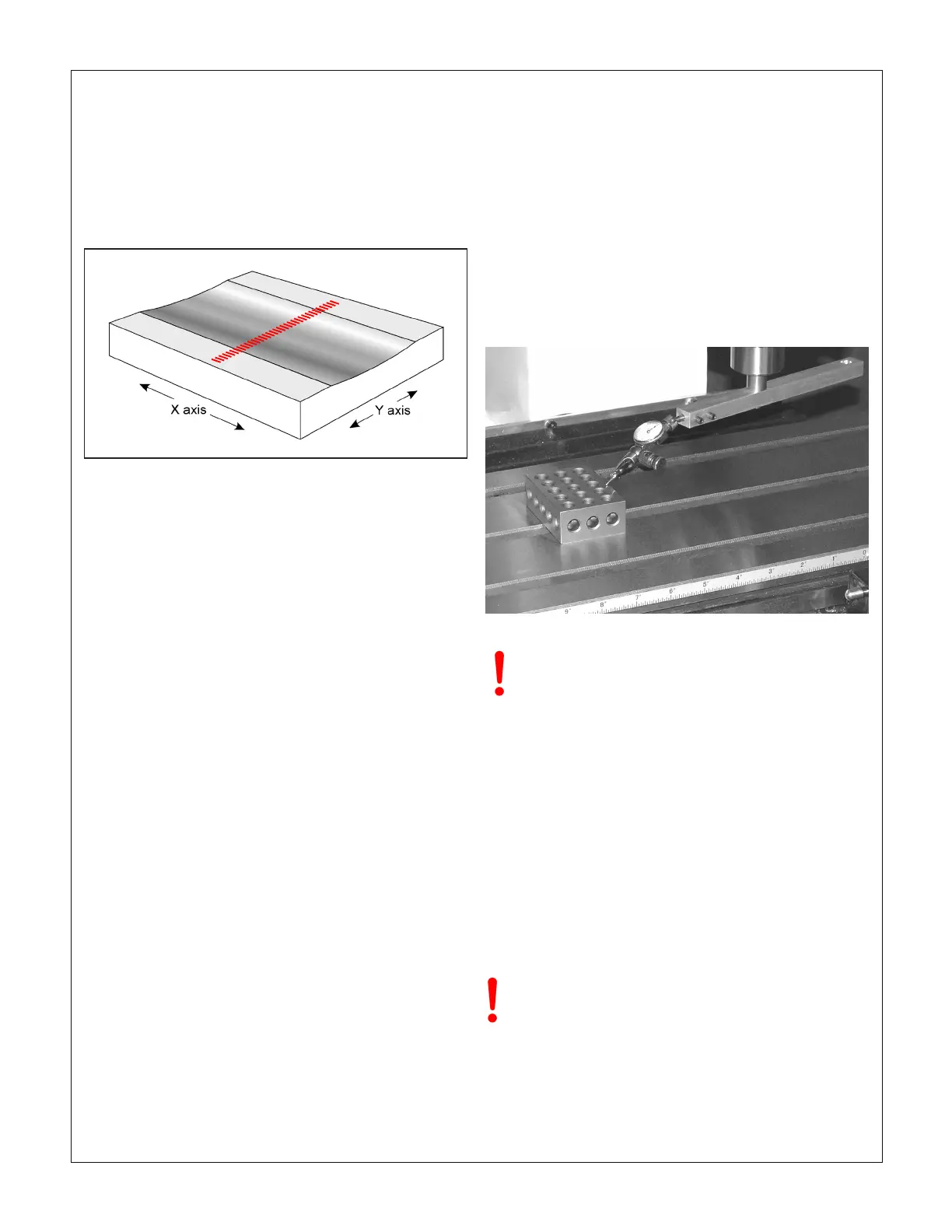
Figure 3-18 Head tilt aects surface atness
This is the eect, much exaggerated, if the head is tilted minutely out
of square when milling a surface with a large diameter cutter. In the
other axis the scalloping eect would be at right angles (hashed red
line) if the head is tilted forward or back, and the table is moved in the
Y-axis.
In all bench mills there is a tendency for Y-axis tram to
vary minutely as the headstock elevation is changed
— select the "most used zone" when shimming

 Loading...
