16
PM 728V-T v2 2020-10 Copyright © 2020 Quality Machine Tools, LLC
Figure 4-1 Gib adjustment, X and Y axes
The left adjustment screw for the X axis is in a similar location to (1)
on the left side of the saddle casting. The back adjustment screw for
the Y axis gib (2) is under the solid rubber way cover behind the table.
Section 4 MAINTENANCE
Unplug the 110V power cord before any
maintenance operation!
RECOMMENDED LUBRICANTS
One-shot oiler: ISO 68 way oil, such as Mobil Vactra No. 2,
or equivalent
Visible gears such as quill rack and pinion, Z-axis bevel
gears: light general purpose grease, NLGI No. 2, or equiva-
lent
X, Y and Z leadscrews: ISO 68 way oil, Vactra No. 2, or
equivalent
General lubrication of parts not one-shot oiled: General
purpose ISO 68 way oil
GENERAL OILING
Assuming a clean environment – no abrasive particles or ma-
chining debris – lack of proper lubrication is the main cause of
premature wear. There should a small amount of seepage of
oil from the mating surfaces lubricated by the one-shot oiler,
namely the X, Y and Z dovetails. Be concerned if no seepage
is visible.
A high-pressure air line can force sharp particles into the gaps
between machine ways, and is not recommended for removing
debris. Brushing o with a disposable paint brush is preferred.
Operate the one-shot oiler every few hours of operation. Use
a dedicated short-bristle brush to apply oil to the leadscrews,
and to the visible portions of the quill rack and pinion.
Remove all machining debris and foreign objects
before lubricating ANYTHING! If need be, any oil is
better than no oil – but use the recommended lubri-
cants when you can.
GIB ADJUSTMENT
Gibs on the X, Y and Z axes control the t of the mating dove-
tailed surfaces. They are gently-tapered lengths of ground cast
iron located by opposing screws at each end. Adjusting them is
a trial and error process that takes time and patience. Aim for
the best compromise between rigidity and reasonably free ta-
2
1
ble movement. Too tight means accelerated wear on the ways
and leadscrews. Too free means workpiece instability, inaccu-
racies and chatter.
Both screw heads must be tight against the gib ends. If you
loosen one, tighten the other. Remove the way covers for ac-
cess to the back of the Y gib and bottom of the Z gib.
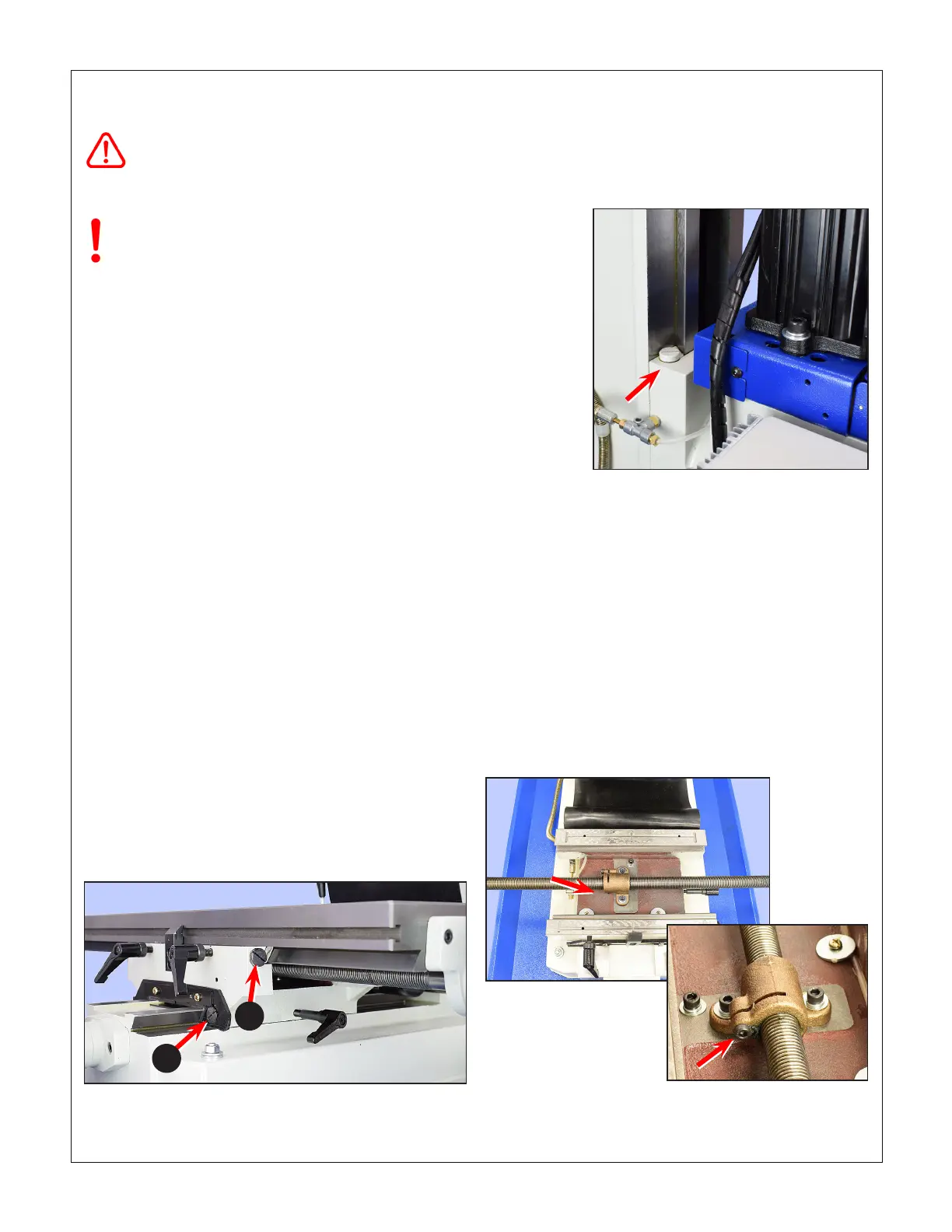
Figure 4-2 Z-axis gib adjustment, upper screw
The lower screw is under the solid rubber way cover.
LEADSCREW BACKLASH CORRECTION
When alternating between clockwise and counter clockwise ro-
tation of the X or Y leadscrews, the handwheel moves freely a
few degrees but the table stays put. This is backlash, a feature
of all leadscrews other than the precision type found on CNC
machines. The acceptable amount of lost motion depends on
the user, but between 0.005” and 0.010" is generally a good
compromise. Smaller numbers are possible, but overdoing it
can lead to premature wear of leadscrew and nut.
Excessive backlash can be corrected by compressing the
leadscrew split nut. For the X-axis this is done by tightening
the socket head screw in Figure 4-3. Use a long-handled 4 mm
hex wrench, or (better) a multi-tool with a 4 mm insert.
Figure 4-3 Table (X-axis) leadscrew nut adjustment
Table removed for visibility. The screw is accessible from the
left side with a long-handled 4 mm hex wrench. Also seen in
this photo are machined oil grooves fed by the one-shot oiler.

 Loading...
