3
PM 728V-T v2 2020-10 Copyright © 2020 Quality Machine Tools, LLC
THESE ARE THE MAIN POINTS TO WATCH OUT FOR!
But read the following pages for more information
• Handling the mill is at least a two-person job.
• Lower the center of gravity by hand-cranking the headstock down until the spindle nose
is just clear of the table.
• Lifting gear – sling, hoist or forklift – must be rated for at least 500 lb.
• The working location of the mill must allow: Full left-right travel of the table, also access
to the top of the column (for Z-axis leadscrew maintenance).
• Power requirement is 110V, 60Hz, 1φ, 20A circuit protection.
• Extension cord not to be used
• Before connecting power for the rst time be sure that:
1. The machine is on a rm footing, adequately secured to bench or stand.
2. No chuck or collet is installed.
3. The drawbar has been removed (see below).
4. There are no clamps or locks on moving parts.
5. The speed control knob is set for the lowest speed.
Section 1 INSTALLATION
SETTING UP THE MILL
The PM-728V-T is shipped in two packing cases, one for the machine and tray (and optional 3-axis DRO), one for
the stand, if ordered.
UNCRATING & MOVING THE MILL
The following procedure makes use of an engine hoist, min-
imum weight rating 500 lb. If a hoist is not available, and you
need to use manpower for lifting, see the dismantling instruc-
tions on the following page.
First, no matter what the lifting method is, prepare the bench or
optional stand, with the chip tray in its working location.
Highly recommended! Bolt the bench or stand rmly to the
oor. Check working clearances, Section 2.
1. If the handwheels were shipped loose, install the largest
of the four at the top of the column. The three smaller
handwheels are for the X-axis (2) and Y-axis (1).
2. Release the table locks, X-axis and Y-axis.
3. Release the headstock Z-axis locks.
4. Center the table (X-axis), then move the table back to the
column as far as it will go (Y-axis).
5. Crank the headstock (Z-axis) down so that the spindle
nose is just clear of the table. The mill’s center of gravity
should now be as far down and back as possible. Tight-
en the Z-axis lock.
6. Unscrew the four nuts securing the mill to the pallet.
7. If necessary, setup the hoist with its legs straddling the
machine as follows: 1. Remove one leg from the hoist,
then position the other leg over the pallet, as close to
the machine base as possible. 2. Re-install the removed
leg, positioning it over the pallet, likewise close to the
machine base. 3. Set the hoist arm short enough so that
the hook is immediately overhead the collar.
8. Run a padded sling under the headstock, as Figure 1-2.
9. Taking care not to damage the Z-axis locking handle
and the electrical box, hook the sling, basket style, to the
hoist's hook/chain.
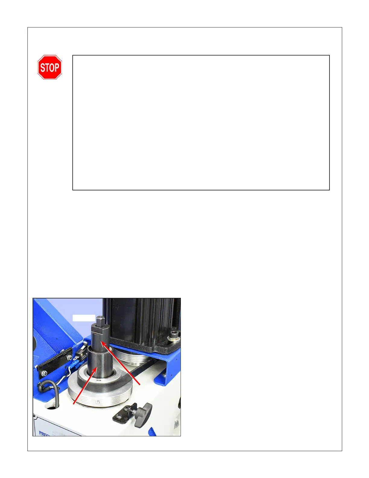
Figure 1-1 Access to the drawbar
Removing the drawbar
1. With the table protected by scrap material, loosen the
quill lock lever, then lower the quill.
2. Swing open the drive cover in front of the motor, Figure
1-1.
3. While holding the spindle nose with the special C-wrench
(supplied), use a 17 mm wrench to unscrew and remove
the spindle cap. See also Figures 3-3 and 3-4.
4. Remove the drawbar from the spindle. Re-install the spin-
dle cap, hand-tight.
Return
spring
cup
Spindle
cap
Drawbar

 Loading...
