6
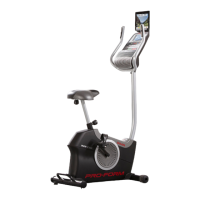
STEP 3
Pull the broaching (7) under the saddle tube, then
insert the saddle adjust set(17) into the “D” shape
tube of the saddle tube set, unclench the broach-
ing. (Front and back movement of the saddle: sad-
dle can be adjusted front and back if users feel
they sit too front or too back of the saddle during
the exercise. Firstly, pull the broaching (7) out and
don’t unclench, then move the saddle adjust set
(17) to the ideal place, unclench the broaching and
fasten it.) See picture 4-A.
Screw off the nut under the saddle(14), then put the
saddle (14) into the saddle xed broaching of the
saddle adjust set, then screw down the nut.
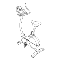
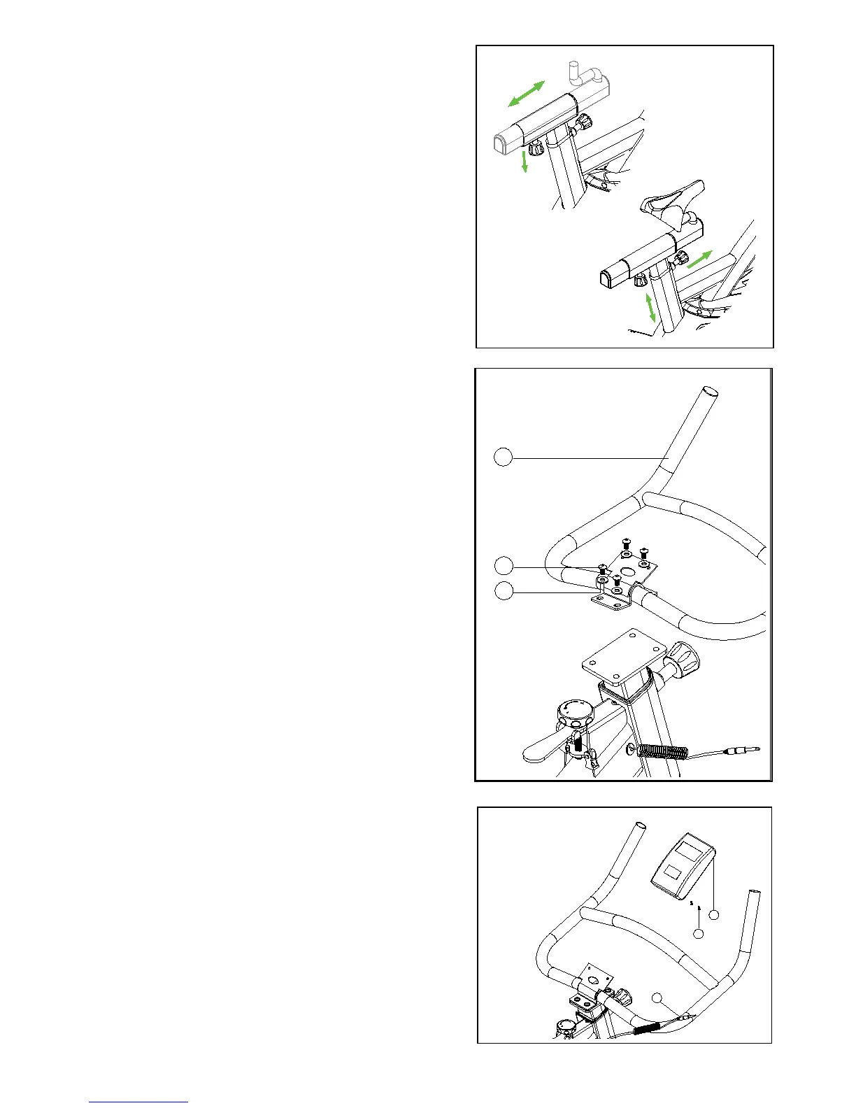
STEP 4
Take down the screw M8*16 (4) which are installed
onto the handle bar ex tube. (5).
Attach the handle bar set (3) onto the handle bar
xed piece of the handle bar ex tube(5),make the
screw M8*16 (4) transx the xed piece of the han-
dle bar tube(3) and the xed piece of the handle
bar ex tube set(5) and fasten them.
STEP 5
Take down the computer xed screws (2) which
are installed onto the computer(1), then attach the
computer to the computer xed piece of the handle
bar tube set (3),fasten it with the screws which have
been took off. Finally, insert the reaction connec-
tion wire (52) into the hole of the SENSOR INPUT.
4
3
56
2
1
52

 Loading...