Page 12
9.6 Battery Capacity
It is recommended that the rechargeable battery used with the Atlas 4 control panel should be capable of powering the
alarm system for a minimum of 8 hours, and that this time period should include 20 minutes of bell/strobe operation.
The minimum battery capacity should be calculated from the current consumption of the individual system components.
A typical example based on the following individual parts is shown below:
Non alarm current for control panel (7hrs 40min) : 130mA (0.130 A)
Steady state current for detectors : 120mA (0.120 A)
(e.g. 8 x 15mA for 8 hours - Pyronix PIRs)
Typical standby current for external sounder : 50mA (0.050 A)
(e.g. Self Actuating Bell for 8 hours)
Typical on state current for external sounder (20 mins) : 350mA (0.35 A)
Alarm state current for control panel (20 mins) : 130mA (0.13 A)
Typical current for external strobe (8 hours) : 150mA (0.15 A)
Alarm condition for 20 mins (0.333 hrs)
Alarm state current for control panel : 0.130
8 detectors @15mA : 0.120
External sounder : 0.350
External strobe : 0.150
Standby current for external sounder : 0.050
Single remote keypad : 0.015
Required capacity for alarm condition = 0.815 x 0.333 = 0.271 Ahrs
Capacity required for standby 7hrs 40 mins (7.67 hrs)
Non alarm current for control panel : 0.130
8 detectors @ 15mA : 0.120
Standby for external sounder : 0.050
Single Remote keypad : 0.015
Required capacity for standby condition = 0.465 x 7.67 = 3.57 Ahrs
Total minimum required battery capacity = 0.271 + 3.57 = 3.84 Ahrs
For this example it is recommended that you use a battery of not less than 6 AH.
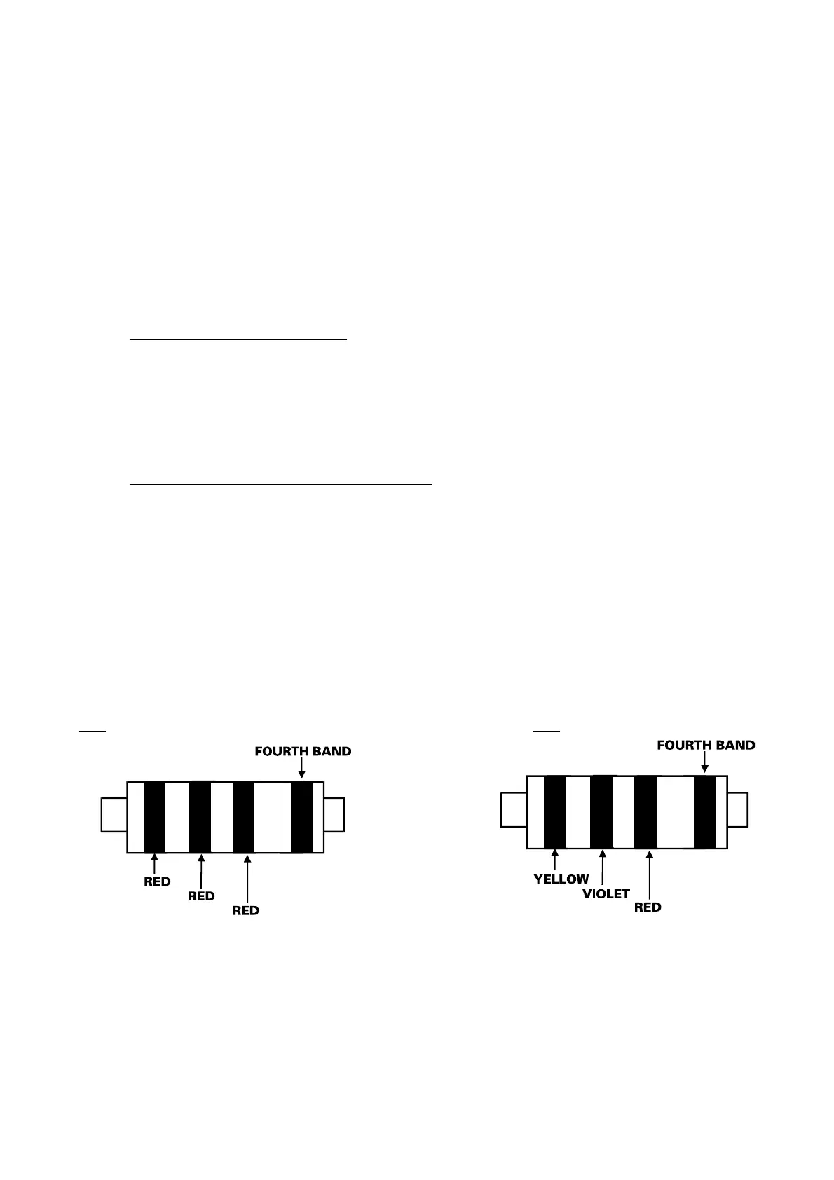
9.7 End of line resistors
When a Sensor, and tamper are wired into the same zone this is called an End of Line Zone (EOL). The Atlas 4 panel
uses resistors on all of its end of line zones. Two resistor values are used, these are 2K2 and 4K7.
To identify the two resistors, coloured bands on the body are used. These are as follows:
2K2
4K7
Any unused zones should NOT be left open circuit. These should have a 2K2 resistor inserted, Refer to diagram 9.7.1,
page 13.
NOTE: when the panel and sensors are wired using end of line resistors, to enable the zone to detect alarm and tamper,
the system must be configured in System Option 1. Refer to Page 17.
 Loading...