2.3.2 Speaker connections
Warning: All PTH series amplifiers are capable of producing
dangerously high voltages at the output terminals! To avoid
cable overheating, do not use speaker cables under 1.5 mm
2
cross-section (AWG 15). The use of thicker cables helps to
keep power loss down and damping high, especially if long
distances have to be bridged. After insertion, make sure that
every speakon connector has been twisted clockwise before
locking it with the swivel nut to ensure proper contact. The pin
configurations for the three speaker connectors are printed on
the amplifier's back panel. The speaker outputs are wired so
they can be used in different ways, depending on the setting of
the mode switch. Before connecting the speakers, make sure
that your speaker cables are properly wired.
DUAL mode: use the SPEAKER OUT 1 and 2 outputs to
connect the speaker systems. The BRIDGED OUT also
carries both output signals and can be used to feed the output
signal to an additional device, e.g. feedback for a speaker
system processor. Minimum total speaker impedance per
channel is 2 ohms.
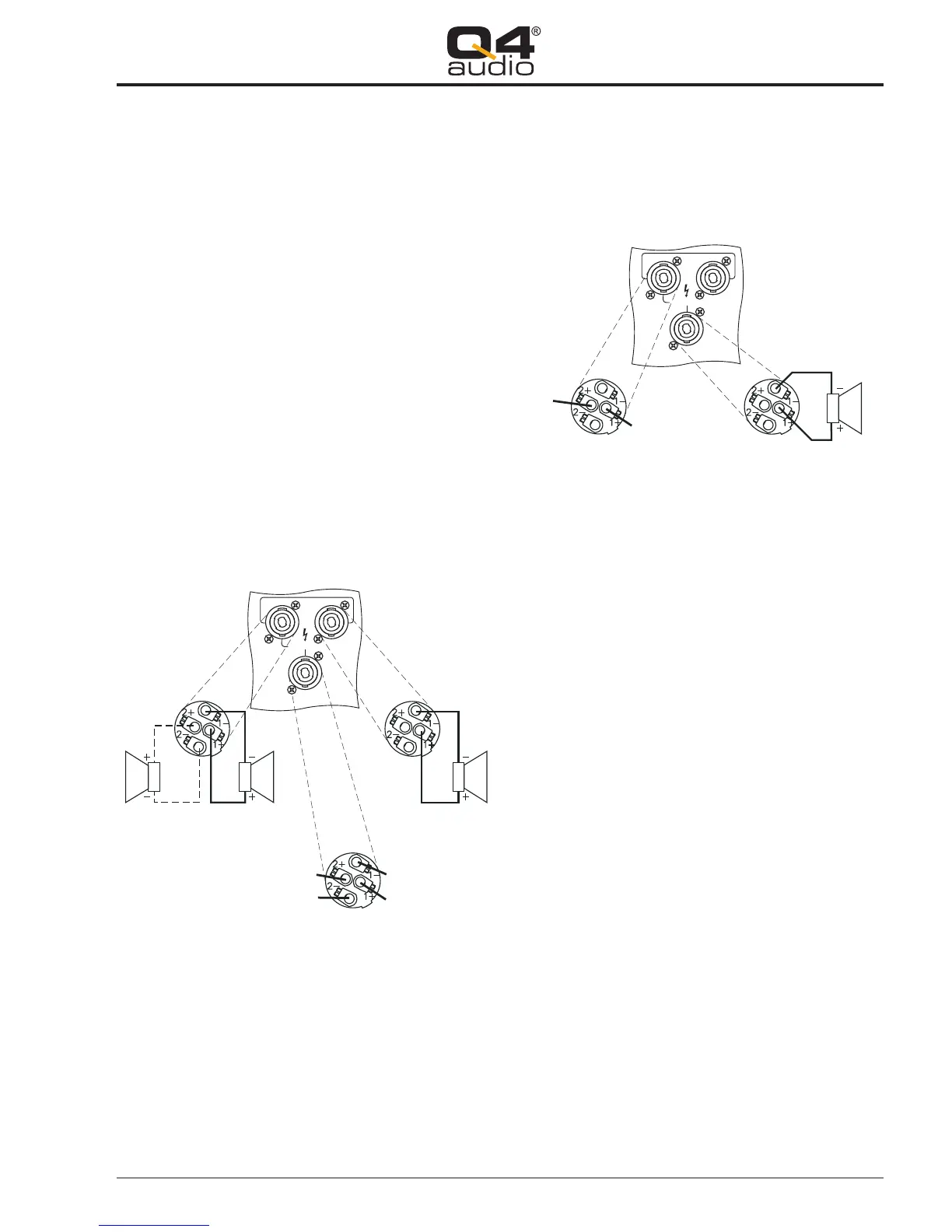
Pin configuration for SPEAKON plugs
Dual (stereo)/Parallel (mono) mode:
PARALLEL mode: same wiring as DUAL mode, but with
identical signals on all outputs. Minimum total speaker
impedance per channel is 2 ohms.
BRIDGE mode: BRIDGED OUT speaker connection is done by
using standard Speakon cables. Make sure that there is no
ground connection for pins 2+ and 2- on your Speakon plug.
The OUT 1 socket can be used to feed the output signal to an
additional device, e.g. feedback for a speaker system
processor.
Pin configuration for SPEAKON plugs
Bridge mode:
2.3.3 Mains connection
For mains connection, use only three-prong mains connectors
with earth contact.
Switching the amplifier to different voltage systems is done
from the inside and should only be performed by a qualified
technician.
The mains cable conductors have the following color code:
YELLOW/GREEN = earth (PE)
BROWN = live (L)
BLUE = neutral (N)
3. Operation
Each channel is controlled from the front panel by a level
control potentiometer and 4 status LED's. The status LED's
indicate the following operational states of the amplifier:
READY/PROTECT: this two-coloured LED indicates the
state of the output protection relay. It lights up green when
the amplifier is working normally, and turns red whenever
the output is disconnected internally as a result of
malfunction, e.g. DC voltage at the output, output stage
defect, or heatsink temperature exceeding 90°C. After
turning the amplifier on, this LED will remain red for about
5 seconds until the internal supply voltages have set to
their normal values.
SIGNAL: a lit LED indicates an audio signal present at the
channel's output. Threshold level is +10 dBV.
NLR: lights up when the internal limiter needs to
automatically reduce gain because of a significant
deviation between input and output signal shape. This
way the NLR limiter prevents occurrence of gross
SPEAKER OUT
BRIDGED
OUT
MIN. 4 OHM
MIN.
2 OHM
Speaker Out 1
(may also be used as
a 4-pole stereo output)
Speaker Out 2
Bridged Out
(feedback for optional processor)
channel 1 ground
channel 2 ground
channel 2 signal
channel 1 signal
1
2
2
1 2
SPEAKER OUT
BRIDGED
OUT
MIN. 4 OHM
MIN.
2 OHM
Speaker Out 1
(feedback for
optional processor)
Bridged Out
signal -
signal +
1 2
7
PTH SeriesUser Manual
 Loading...