to direct the heated air in the desired direction. When the
heater is installed for horizontal discharge, the louvers should
direct the air either straight ahead or downward. Directing
the air upward may cause the heated air to remain in the ceil-
ing area and waste energy.
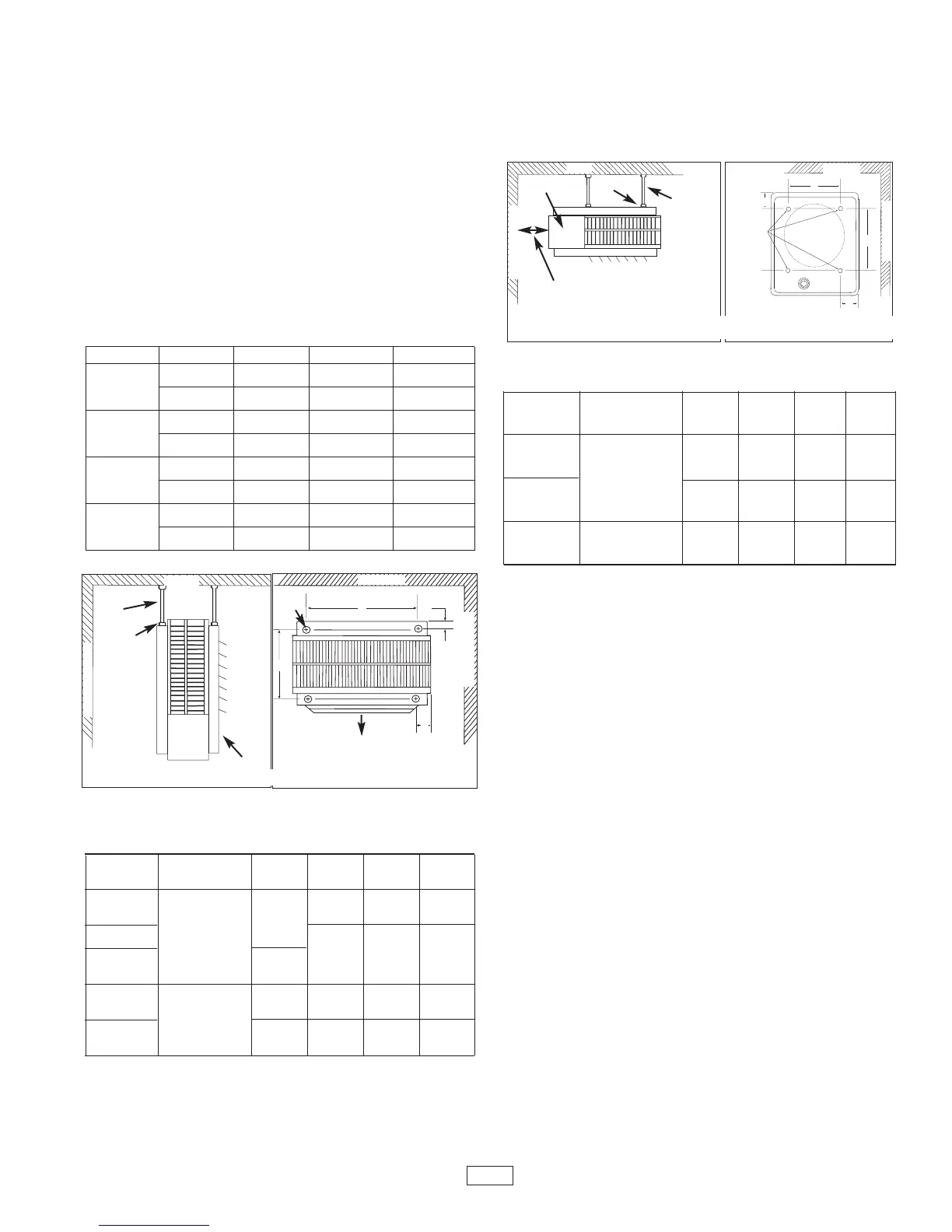
HORIZONTAL DISCHARGE (Rod-mount from Ceiling)
1. Install four threaded mounting rods in the threaded holes
and secure in place using lock nuts. (See Table 2).
2. Securely attach the four mounting rods to the ceiling.
(Refer to Table 1 for wall and ceiling clearances, and
Table 2 for mounting rod spacing).
VERTICAL DISCHARGE (Rod-Mount from Ceiling)
1. Remove bolts from the threaded holes in the back of
the heater.
2. Install four threaded mounting rods in the threaded holes
and and secure in place using lock nuts.
3. Securely attach the four mounting rods to the ceiling.
(Refer to Table 1 for wall and ceiling clearances, and
Table 3 for mounting rod spacing dimensions.)
WIRING
BRANCH CIRCUIT (POWER)
1. Connect heater only to the voltage, amperage and fre-
quency specified on the nameplate.
2. Field wiring must be properly sized to carry the amperage
in accordance with the NEC.
3. The access door is hinged. There are either one or two
screws accessible from the side that must be loosened
to gain access. These screws are the captive type; do not
try to remove them.
4. A knockout is provided in the back of the heater close to the
power terminal block and the control terminal board.
The control terminal board knockout is 1/2 inch (12.7 mm)
conduit size. The power terminal block knockout is multi-
ple diameter. Use the diameter that fits the required con-
duit size.
5. A ground terminal is provided near the power terminal
board. The ground wire should be connected before other
connections are made.
6. The power terminal block is equipped with box terminals
sized to accept the correct size power supply wire.
Branch circuit wire rated min 600V, 60° C is acceptable
for heaters rated up to 80 amps. For heaters rated more
than 80 amps, branch circuit wire must be rated at least
75°C. Either aluminum or copper wire is satisfactory for
connection to the heater power terminal block box terminal.
Copper wire is recommended and must be used with built-
in disconnect switch.
Table 2. Rod Thread and Spacing Dimensions, inches
(mm) for Horizontal Discharge
Rod Thread
Unit Type A B C D
3 - 5 kW
64
1
/
16
3
/
4
6
1
/
16
(152.4) (103.1) (19.0)
7.5 - 10 kW
(153.9)
15 - 20 kW
5
/
16
- 18
11
3
/
8
8
7
/
8
5
1
/
8
3
/
4
(289.0)
(225.6) (130.3) (19.0)
25 - 30 kW
10
9
/
16
14 - 12 6
3
/
16
5
/
8
(268.2) (368.3) (157.2) (16.0)
40 - 50 kW
3
/
8
- 16
15
15
/
16
14 - 12 6
3
/
16
5
/
8
(404.9) (368.3) (157.2) (16.0)
Unit Discharge Ceiling Side Wall Back Wall
3 & 5 kW
Horiz. 2 (50.8) 6 (152.4) 9 (228.6)
Vert. 6 (152.4) 18 (457.2) 18 (457.2)
7.5 to 10 kW
Horiz. 6 (152.4) 6 (152.4) 13 (330.2)
Vert. 6 (152.4) 24 (609.6) 24 (609.6)
15 to 10 kW
Horiz. 6 (152.4) 9 (228.6) 12
1
/
2
(317.5)
Vert 6 (152.4) 24 (609.6) 24 (609.6)
25 to 50 kW
Horiz. 16 (406.4) 12 (304.8) 18
1
/
2
(470.0)
Vert. 12 (304.8) 39 (914.4) 39 (914.4)
Figure 2. Vertical Discharge Mounting and Rod Spacing
Table 3. Rod Thread Type and Spacing Dimensions, inch-
es (mm) for Vertical Discharge
Rod Thread
Unit Type E F G H
3 - 5 kW
69
3
/
4
24
1
/
16
5
/
16
- 18
(152.4) 247.7) (50.8) (103.1)
7.5 - 20 kW
8
7
/
8
14
5
/
8
25
1
/
8
(225.6) (371.6) (50.8) (130.3)
25 - 30 kW
3
/
8
- 16
14
1
/
2
21
1
/
4
2
3
/
16
6
3
/
16
(368.3) (539.8) (56.0) (157.2)
Table 1. Wall and Ceiling Clearance, inches (mm)
 Loading...