CONTROL WIRING
LINE VOLTAGE IS PRESENT ON SOME OF THE TERMINALS
ON THE CONTROL TERMINAL BOARD. ALWAYS DISCON-
NECT THE POWER FROM THE HEATER BEFORE MAK-
ING ANY CONNECTIONS TO THE CONTROL BOARD TO
PREVENT ELECTRIC SHOCK HAZARD.
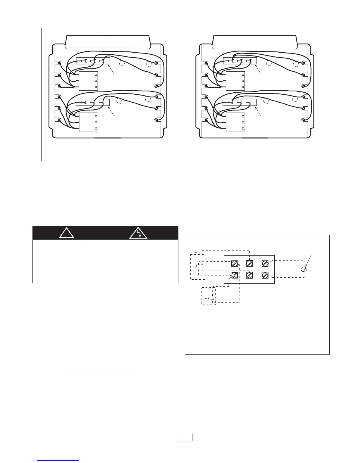
Figure 4. Control Terminal Board
(for Heaters Without Contactors)
NOTES:
1. THIS STYLE CONTROL TERMINAL BOARD
USED WITH MODELS MUH0321, MUH0371,
MUH0381, MUH0521, MUH0571, AND
MUH0581.
2. WHEN UNIT IS WIRED FOR SINGLE-PHASE,
JUMPER H1 TO H2. IF SINGLE-POLE THER-
MOSTAT IS USED WITH SINGLE-PHASE
UNIT, CONNECT THERMOSTAT LEADS TO
P1 AND H1.
3. EXTERNAL LINE VOLTAGE THERMOSTATS
SHOULD BE TREATED AS SINGLE STAGE
ONLY.
5
!
WARNING
1. Use min. 600 volts, NEC Class 1 insulated wire for all
control circuit wiring.
2. Use a crimp-on type fork terminal on the wire ends that
attach to the control terminal board if more than one
connection is to be made under the terminal screw.
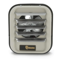
3. On units not provided with internal contactor
(3 & 5 KW),
refer to Figure 4 for wiring diagram.
Note: Thermostat and control circuit wiring must be suit-
able to handle the full load of the heater (example
MUH0581 is rated 24 amps)
4. On units provided with internal contactor
(units rated 7
KW and higher) refer to Figure 5 for wiring diagram.
Control wiring must be rated minimum 18 AWG.
 Loading...