LTE Module Series
EM05 Hardware Design
EM05_Hardware_Design Confidential / Released 28 / 59
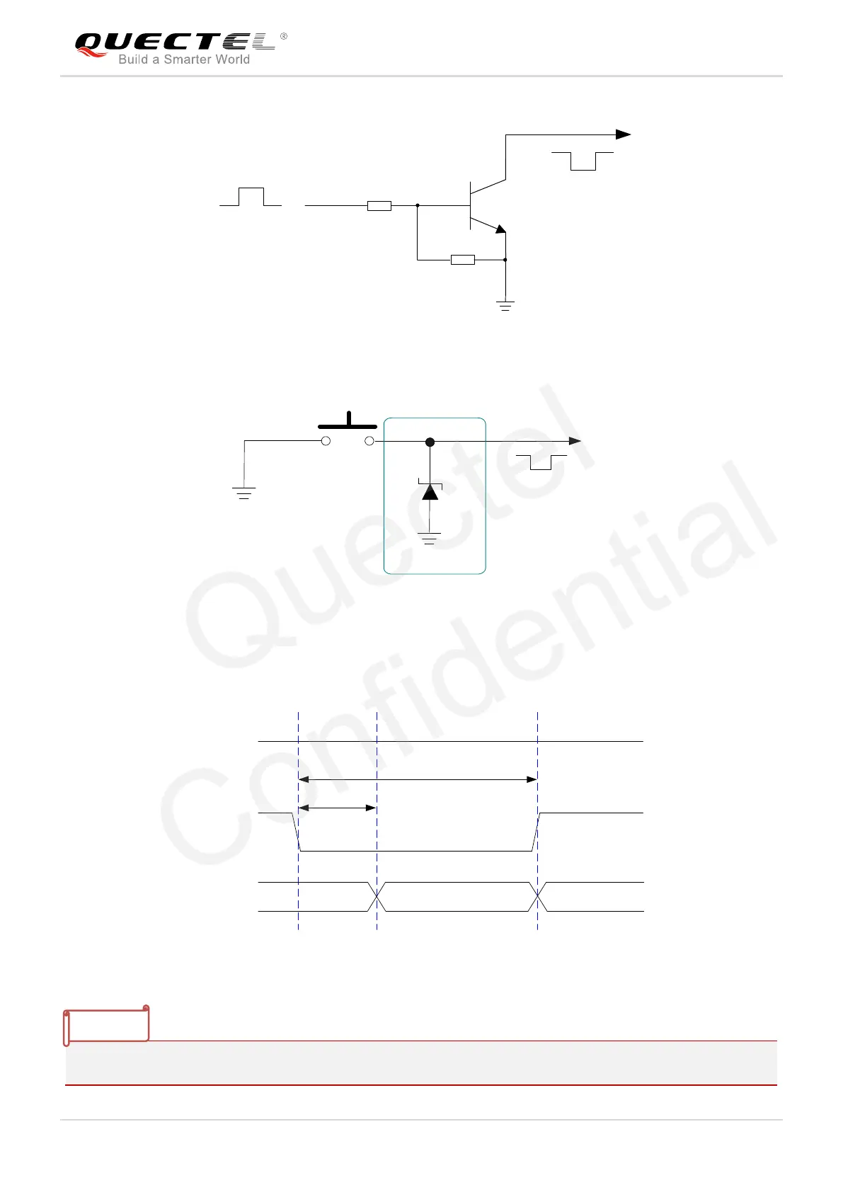
Figure 13: Reference Circuit of RESET# by Using Driving Circuit
Figure 14: Reference Circuit of RESET# by Using Button
The reset scenario is illustrated in the following figure.
V
IL
≤0.5V
V
IH
≥1.3V
VCC
≥150ms
Resetting
Module
Status
Running
RESET#
Restart
≤460ms
Figure 15: Timing of Resetting Module
Please ensure that there is no large capacitance on RESET# pin.