GNSS Module Series
LC79D Hardware Design
LC79D_Hardware_Design 28 / 42
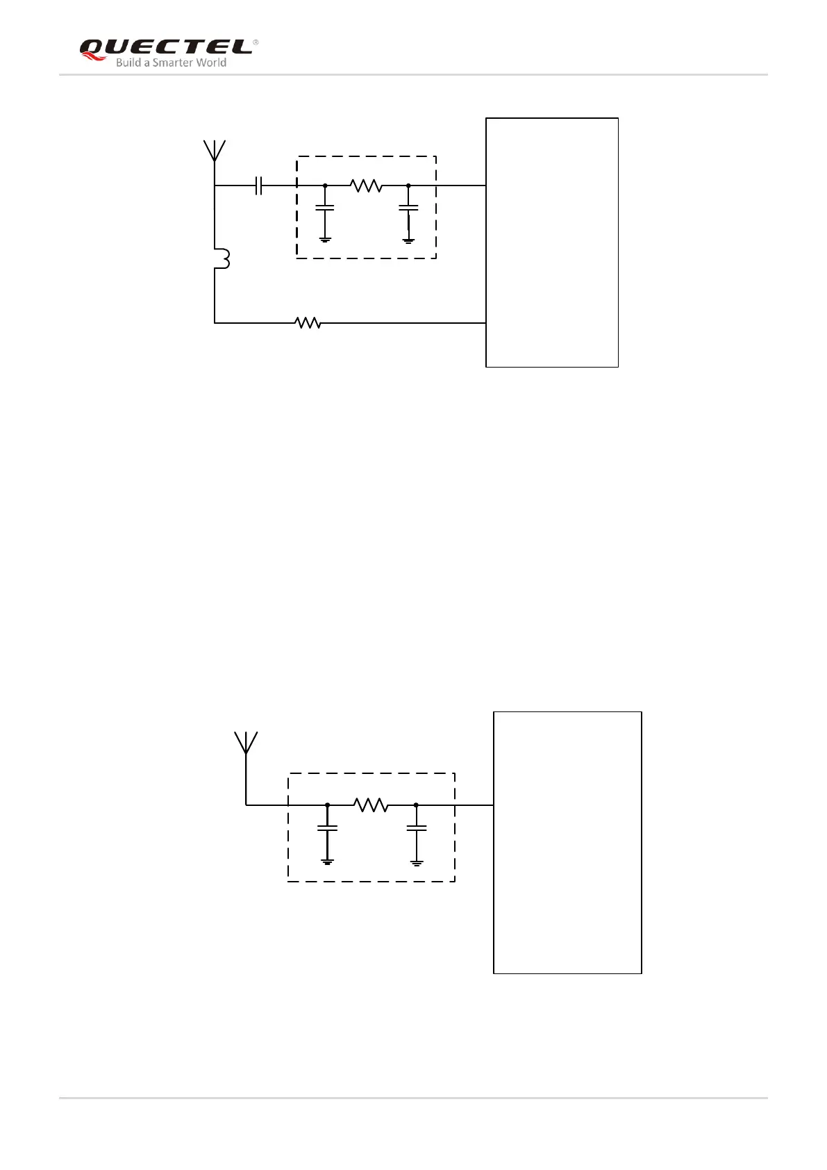
Active Antenna
L1 68nH
R2 10R
C2 NM
C3 NM
R1
П Matching Circuit
0R
LC79D Module
RF_IN
C1 100pF
VCC_RF
Figure 10: Reference Design for Active Antenna
C1 is used to block DC from VCC_RF. C2, C3 and R1 are reserved matching circuits for antenna
impedance modification. By default, R1 is 0Ω, C1 is 100pF, while C2 and C3 are not mounted.
The inductor L1 is used to prevent the RF signal from leaking into the VCC_RF and route the bias supply
to the active antenna. The recommended value of L1 is no less than 68nH. R2 can protect the whole circuit
in case the active antenna is short-circuited to ground.
4.2.2. Passive Antenna Reference Design
The following figure is a typical reference design for passive antenna.
Passive Antenna
RF_IN
C1 NM
C2 NM
R1
П Matching Circuit
0R
LC79D Module
Figure 11: Reference Design for Passive Antenna
 Loading...


