5
6. Set the dip switch positions inside the Hub as shown in the Figure 3.1A.
7. Power-on the Hub. The Power LED indicator will be lit.
8. Press the Test button to make sure the fan works. The Test LED indicator will blink three times
every two seconds indicating 1-speed and the fan will be on. Press the Test button again and
the fan should shut off and the LED will be off.
9. If the fan doesn’t operate as described in step 9, please check the dip switch position.
3.2 TWO SPEED WIRING
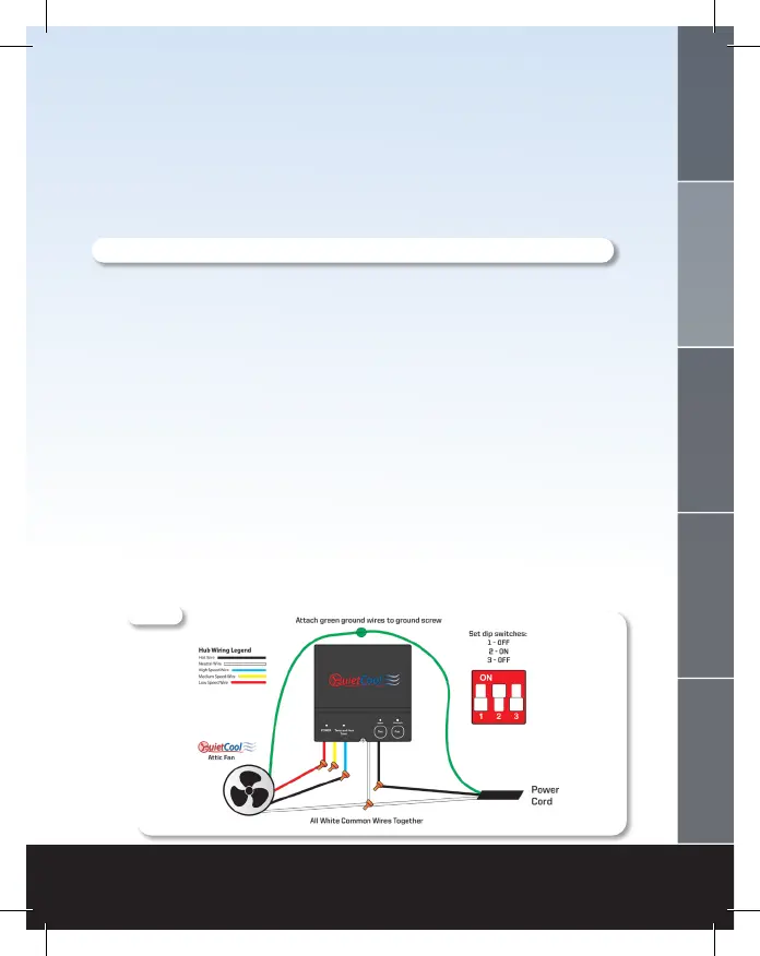
1. Using a wire nut, connect the black wire from the power source to the black wire from
the Hub.
2. Connect the white wire from the power source and the white wire on the fan to the white
wire from the Hub.
3. Connect the black wire from the fan to the blue wire on the Hub.
4. Connect the red wire from the fan to the red wire on the Hub.
5. Cap the yellow wire from the Hub.
6. Ground the green wire from the fan and the green wire from the power cord to the ground
screw in the Hub.
7. Set the dip switch positions inside the Hub as shown in the Figure 3.2A.
8. Power-on the Hub. The Power LED indicator will be lit.
9. Press the Test button to make sure the fan works. The Test LED indicator will blink three
times every two seconds indicating 2-speed and the fan will be on high. Press the Test button
again and the fan will switch to low speed and the Test LED indicator will blink once every
two seconds. Press the Test button again and the fan should shut off and the LED will be off.
10. If the fan doesn’t operate as described in step 9, please check the dip switch position/wiring.
Figure 3.2A
WELCOME
INSTALLATION
WIRING OPERATION
WARRANTY
 Loading...