4
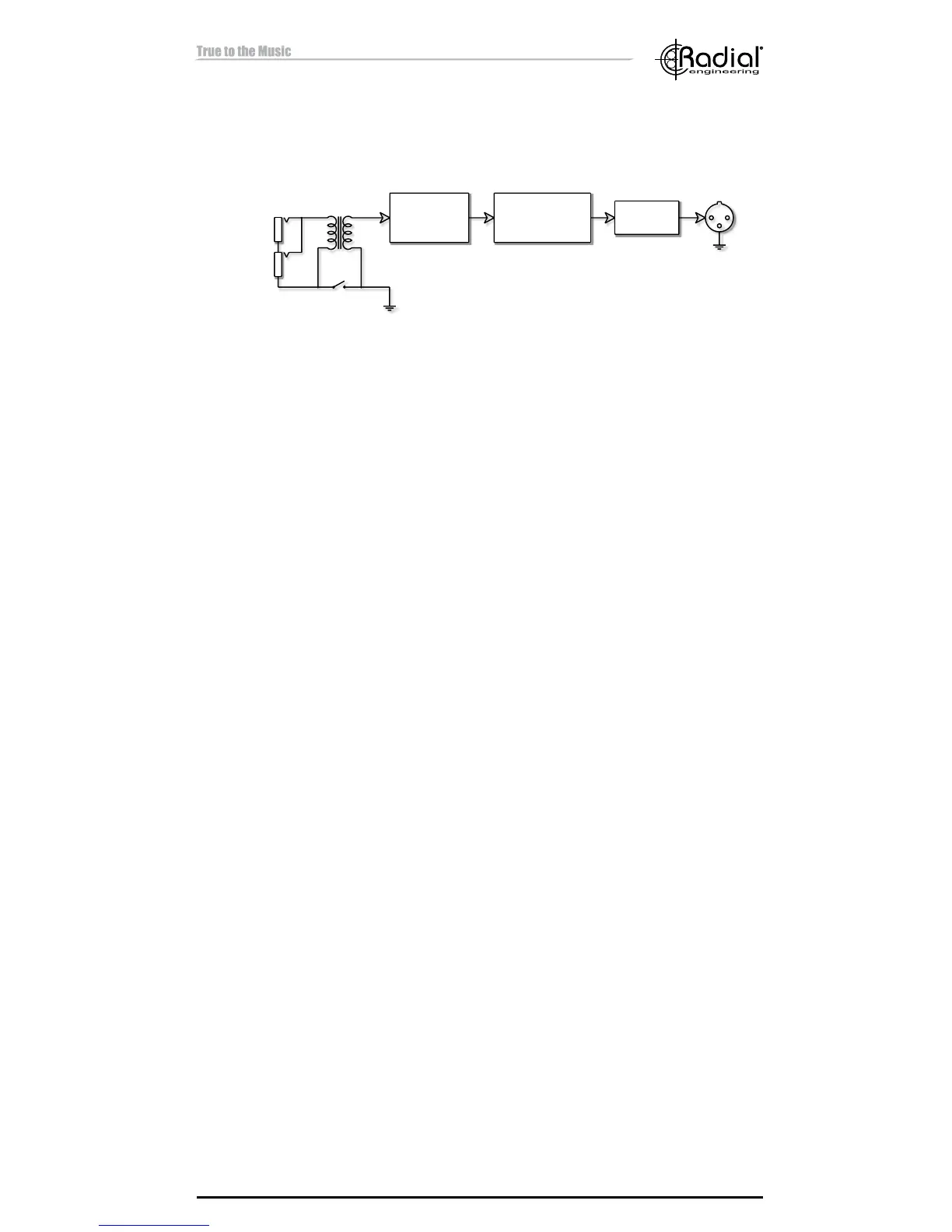
SIGNAL FLOW
To help you understand how the JDX 48 works take a few moments to
trace the signal ow through the block diagram.
FROM AMP
TO SPEAKER
ACTIVE
BANDPASS
FILTER
ACTIVE
BALANCED
DRIVER
POLARITY
REVERSE
BALANCED
XLR OUTPUT
TRANSFORMER
REACTIVE LOAD
GROUND
LIFT
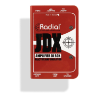
Amplier Input and Speaker Thru-put: The FROM AMP input and TO
SPEAKER thru-put jacks are paralleled together and provides the means
to patch the JDX 48 in-between the amp output and loudspeaker.
Transformer: The transformer is the front end of the JDX 48 circuit and is
used as a reactive load that responds to the various electrical phenomena
that dictate how a particular amplier and loudspeaker sound together.
This is what makes the JDX 48 unique when compared to the “load box”
approach. A load box simply burns off the excess energy into heat and
completely ignores the amp and loudspeaker interaction. By capturing
the reactive effect between the amp and loudspeaker the JDX 48 comes
closer to the original tone than any other interface system.
The transformer also pulls double duty by electrically isolating the signal
passing through it, effectively blocking noise caused by ground loops. This
is important because the JDX 48 connects a guitar amplier to a recording
or PA system that may be powered from a different AC main circuit. Without
the transformer a ground loop may form that can cause buzz and hum.
Ground Lift: A ground lift switch is provided to further reduce noise
caused by ground loops.
Active Bandpass Filter: The analog lter section emulates the response
curve of a 4x12 speaker cabinet.
Active Balanced Driver: The output driver in the JDX 48 converts the
output to a balanced 600Ω mic-level signal for driving long cables without
signal loss or noise. This JDX 48 output can be patched into typical mi-
crophone snakes and be processed along with other microphone signals.
The active balanced driver employs a discrete Class-A design for excellent
headroom and low distortion.
180° Polarity Reverse: The polarity of the JDX 48 output can be inverted
with the 180° switch. Depressing the switch will reverse the signal on pin-2
and pin-3 at the XLR output. The polarity reverse is helpful to phase align
two signals when used to interface older "pin-3 hot" equipment that does
not follow the AES standard for XLR pin-out.
 Loading...