www.raisecom.com User Manual
5
Chapter 3 Device Appearance and Descripiton
3.1 Device front panel
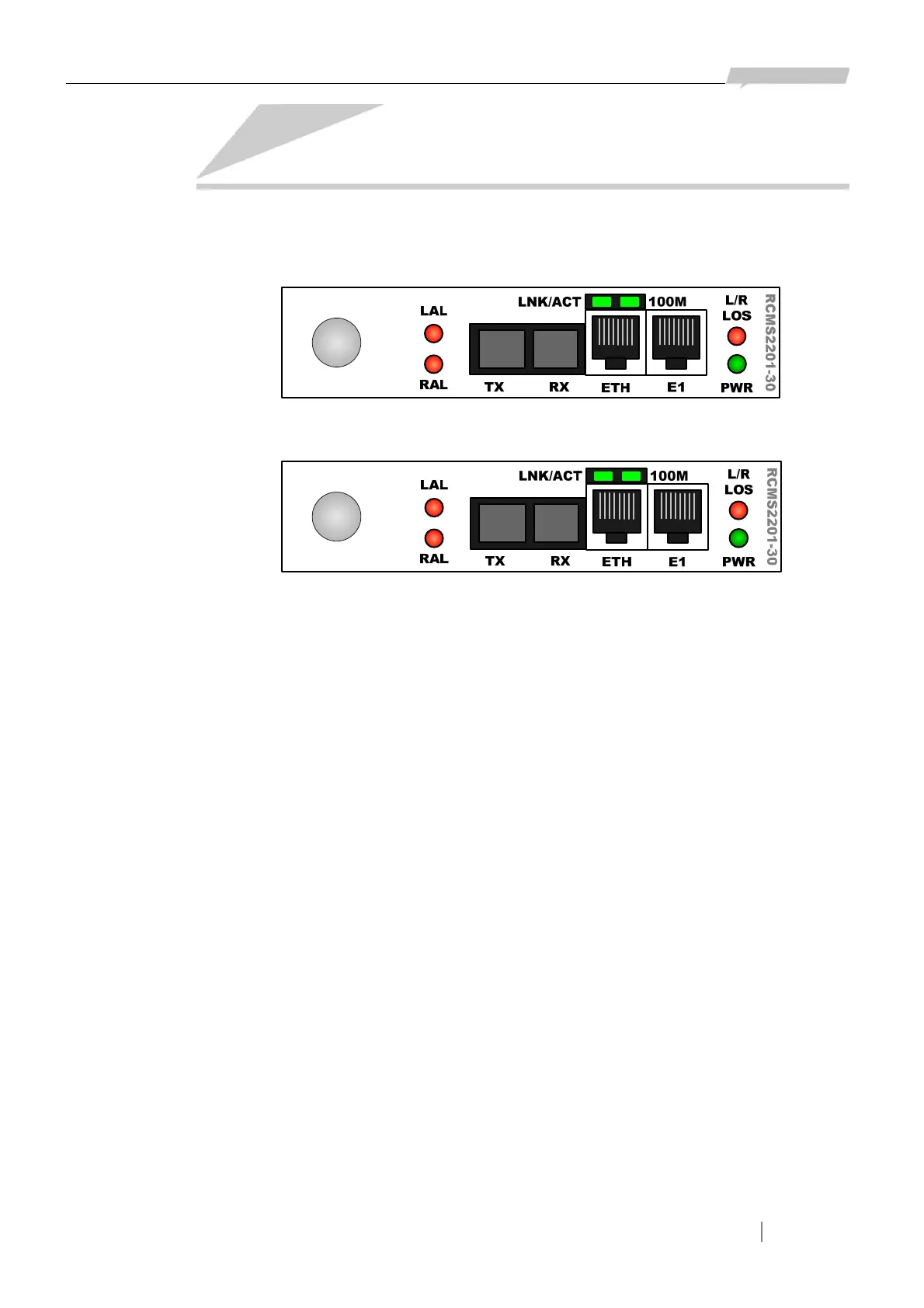
Figure 3-1 The front panel of RC832-30
Figure 3-2 The front panel of RC832-30-BL
3.2 Indicator description
Power supply indicator:
¾ PWR (Green): power supply working status indicator
ON: the power supply is working normally
E1 indicator:
¾ LLOS (Red): local loss of E1 signal alarm indicator
¾ RLOS (Red): remote loss of E1 signal alarm indicator
Optical interface indicator:
¾ ALM/LPR (two-color): optical interface alarm indicator
Red ON: local optical interface total alarm, at lease one of LOS alarm, LOF alarm, E-3 alarm
and E-6 alarm occurs at the local optical interface
Red Flickering: remote optical interface total alarm, no alarm occurs at the local optical
interface while at least one of LOS alarm, LOF alarm, E-3
alarm and E-6 alarm occurs at the remote optical interface.
Yellow ON: both the local and remote device is working normally when the remote system is
power down.
3.3 Interface description
RC832-30
 Loading...