,
4
,’
ST!%
plus Depth Operation and Installation Handbook
1
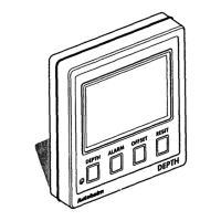
Cable boss 2 Fiiing studs
3lhumb
nuts
4Gashet
1.2 Mounting Procedure
1.
Make sure that the selected location is
clean,
smooth and flat.
2.
Apply the self-adhesive template (supplied) to the selected location and
mark the centres for the fHing studs (2) and the cable boss
(1).
3.
Drii two 4mm
(5/32in)
clearance holes for the fixing studs
(2)
through
the bulkhead. Remove the template.
4.
Cut the clearance hole for the cable boss
(1)
using a 50mm (2in)
diameter cutter.
5. Screw the two fixing studs
(2)
into the control head.
6.
Pass the SeaTalk cable and transducer tails through the cable-boss (1)
clearance hole.
7. Assemble the contiol head to
tie
bulkhead and secure from behind
using the thumb nuts
(3).
Note:
The rear case is fitted with a foam gasket to form a water-tight seal between
the instrument and the selected installation face. Under no circumstances
must silicone greases be applied to this gasket as an additional method of
sealing-the silicone will expand and distort the
rear case.
ChaMer 1: Control Head Installation
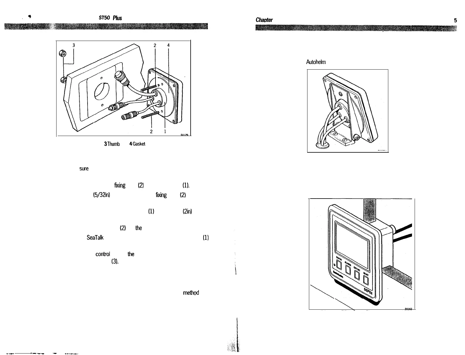
Bracket Mounting
The ST50 Plus Depth can, as an alternative, be bracket mounted using the
Autohelm Mounting Kit.
Flush Mounting
A flush mounting kii is available for installations where a flush mount is
required or more desirable. Full installation instructions are provided with
the kit.
---
e--m._
-
--._-___
 Loading...