www.SteamPoweredRadio.Com
TABLE
OF
CONTENTS
Title
Technical Summary
.........
....
,
...........................................................
.
Electrical Characteristics
....
...................
........
..
..................
......
.....
...
.
Tube Complement . .
..
...
..
............
...
..
.
....
........
. . .
.. ..
.
.......
....
..
..........
. ·
Mechanical Specifications
...................................
·.·
...........................
.
Description
......................................•.....................••...................
Purpose
....
,
....................•.......••....
.
.....
.
.........••
..••.•
...........•....
Construction
..
...
.............
....•....
. •
.•.....
..
..
. .
..
..........•........••..........
Circuit
.........................•.....••...............................................
Installation
Mounting
...................................................................•..........
R-F
Connecfions
.........•...........................................................
,
..
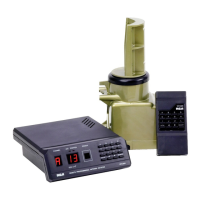
Remote Metering and
Audio
Monitoring
.................................
·•· . .
...
....
...
.....
.
Static Drain
...
.
......•....•..................•...........................................
Tower Lighting,
..
~
.....................................................................
.
Tuning
............
..
.......
....
..
.
.....
.
.....•..•
....
.
..
.
..
....
..
..
............
. .
.........
General Considerations
..
......
..
..
.........•..
....
...
.
.......
......
...
.........
.........
Tuning Procedure with
R-F
Bridge
...
......
.........
.
....
..
.
..
..............................
.
Tuning Procedure without
R-F
Bridge .
..
................
............
...
.
..
.
... ...
.......
. : . . .
Final Check
......................••....••.••...........................................
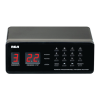
Remote Metering Equipment
...........•.••................................................
Maintenance
................•........••••...•.
, ,
.......
..
.............
,
•...................
Parts
List
.........
.
..
.......................•..•.•...........•.........
...
....
.
.............
ILLUSTRATIONS
Figure
2
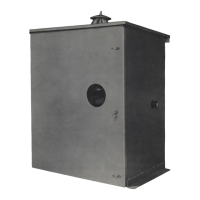
1-Type
BPA-10 Antenna Tuning Unit (Exterior View)
2-Simplified
Circuit Diagram (K-861732)
....
.
... ...
,
...............................•..........
3-Coupling
Circuit and Tuning Unit
Network
(K-861757)
.........................................
.
4-Antenna
Tuning Unit (Interior View)
.............•.....
.
..
......
...
.
........................
5-Antenna
Tunin·g Unit (S;hematic M-428316)
......
..
...
.......
.....
......
.
..
.
.. ..
....•.....•.
6-Antenna
Tuning Unit (Outline M-428610)
.........•............
. · .
......
.
....................
.
Page
3
3
3
3
5
5
5
5
5
5
5
5
5
5
5
5
6
7
8
8
8
9
4
6
7
9
10
11
I
I
I
I
I
I
I
I
I
I
I
I
I
I
I
I
I
I
I
I
I
I
 Loading...