2 INSTALLATION
1. Wire the ‘Common Ground’ wire to a ground point that is common to both the Start
battery (or the Solar Input Ground wire) and the Auxiliary battery to be charged.
This point may be on the chassis of the vehicle, on the chassis of the trailer/
camper/caravan or directly wired to both batteries, depending on your installation
requirements.
2. Wire the ‘Output Battery Positive’ to the Auxiliary battery positive terminal. Ideally
the BCDC unit should be a maximum of 1 metre in cable length from the battery
positive terminal, and should be wired with a minimum of 7.71mm² or 8 B&S
cable.
3. Wire the ‘Input Battery Positive’ wire to either the Start battery positive terminal or
the Solar Input Positive wire, depending on your install. Below is a table outlining
the required cable size for a given cable install length. Always choose a wire
diameter equal to or greater than what is specifi ed below.
NOTE: Appropriate sized fuses MUST be used to protect system wiring, values
noted above are a guide only and fuses should be determined according to
specifi c installation requirements.
Cable Install Length
(m)
Minimum Wire Size
(mm²)
Recommended Wire
Size (mm²)
Closest (BAE, B&S,
AWG)
1 - 5 6 7.71 8
5 - 9 6 13.56 6
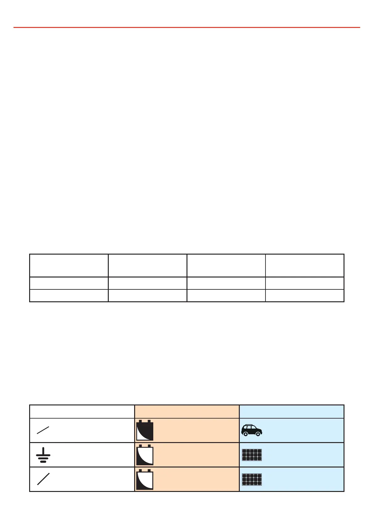
4. Wire the ‘Source Select’ wire according to your installation requirements. For
a setup charging from either a 12V or 24V alternator, connect this wire to the
‘Battery Input Positive’ wire. For a Solar charging setup, connect this wire to
GROUND or just leave it disconnected. This wire is monitored at all times.
5. Wire the ‘Battery Type’ wire according to the type of Auxiliary battery you have
installed. This wire is monitored when the charger is not charging.
Connection Battery type (Orange) Source select (Blue)
Input positive Calcium Alternator charge
Ground Standard Lead Acid Solar charge
Not connected AGM or Gel Solar charge
gl
7
ca
pb
N
C
24V
12V
 Loading...