Fillcontrol Plus Compact — 16.12.2020 - Rev. C
Risk of serious injury or death due to electric shock.
If live parts are touched, there is risk of life-threatening injuries.
• Ensure that the system is voltage-free before installing the device.
• Ensure that the system is secured and cannot be reactivated by other
persons.
• Ensure that installation work for the electric connection of the device is
carried out by an electrician, and in compliance with electrical
engineering regulations.
Risk of injury due to pressurised liquid
If installation, removal or maintenance work is not carried out correctly, there
is a risk of burns and other injuries at the connection points, if pressurised
hot water or hot steam suddenly escapes.
• Ensure proper installation, removal or maintenance work.
• Ensure that the system is de-pressurised before performing installation,
removal or maintenance work at the connection points.
Risk of burns on hot surfaces
Hot surfaces in heating systems can cause burns to the skin.
• Wear protective gloves.
• Please place appropriate warning signs in the vicinity of the device.
Risk of injury due to falls or bumps
Bruising from falls or bumps on system components during installation.
• Wear personal protective equipment (helmet, protective clothing,
gloves, safety boots).
Note!
Confirm that installation and start-up have been carried out correctly
using the installation, start-up and maintenance certificate. This action
is a prerequisite for the making of warranty claims.
– Have the Reflex Customer Service carry out commissioning and
the annual maintenance.
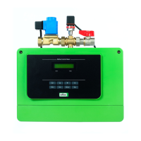
• The nameplate of and the markings on the device provide information
about the manufacturer, the year of manufacture, the manufacturing
number and technical data. Ensure that the temperature and pressure
protection does neither exceed nor fall below the operating parameters.
• The device is shipped with a plug (power unit) and must be connected only
to an earthed power outlet.
6.1 Installation conditions
6.1.1 Incoming inspection
Prior to shipping, this device was carefully inspected and packed. Damages
during transport cannot be excluded.
Proceed as follows:
1. Upon receipt of the goods, check the shipment for
• completeness and
• possible transport damage.
2. Document any damage.
3. Contact the forwarding agent to register your complaint.
6.2 Preparatory work
• The installation location must be a frost-free and well-ventilated space
protected from flooding.
• Ensure adequate distance of the device from the wall.
• The device must be accessible for maintenance, assembly and disassembly.
6.3 Execution
Damage due to improper installation
Additional device stresses may arise due to the connection of pipes or system
equipment.
• Ensure that pipes are connected from the device to the system without
them being stressed or strained.
• If necessary, provide support structures for the pipes or equipment.
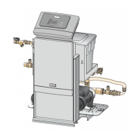
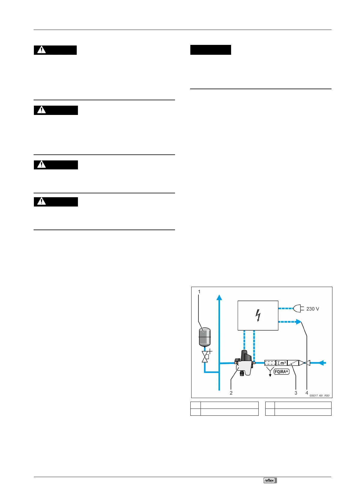
Install the device in the system circuit.
Proceed as follows:
1. Install the appropriate connection line from the mains water system to the
device.
– Prevent any possible stagnation within the water circuit.
2. Install the outlet line from the device to the system circuit.
– Select an appropriately dimensioned outlet line for the device
(length and diameter).
– Take into account that the pressure loss in this line is < 0.3 bar in
every operating mode.
3. Thoroughly purge the lines after installation.
– You will thus prevent damages caused by contamination.
4. Ensure the correct flow direction of the device.
– Note the marking indicating the flow direction at the device housing.
5. Install the device between the connection line from the mains water
system and the outlet line to the system circuit.
– Use the supplied connection threaded connection fitting.
6. Install the drain pipe with sufficient dimensions (length and diameter) at
the device.
– When connecting the funnel to the waste water system, ensure that
you comply with the applicable DIN EN 12056 standard.
The device is installed.
Note!
Use a drinking water in accordance with DIN EN 13443 and a water
metering instrument.
• This will ensure continuous and trouble-free operation.
Note!
When using a water treatment system, use an additional pressure
sensor.
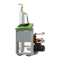
Diaphragm expansion vessel
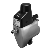
Fillcontrol make-up fitting
 Loading...