Fillcontrol Plus Compact — 16.12.2020 - Rev. C
6.5 Electrical connection
Risk of serious injury or death due to electric shock.
If live parts are touched, there is risk of life-threatening injuries.
• Ensure that the system is voltage-free before installing the device.
• Ensure that the system is secured and cannot be reactivated by other
persons.
• Ensure that installation work for the electric connection of the device is
carried out by an electrician, and in compliance with electrical
engineering regulations.
Risk of serious injury or death due to electric shock
Some parts of the device's circuit board may still carry 230 V voltage even
with the device physically isolated from the power supply.
• Before you remove the covers, completely isolate the device controller
from the power supply.
• Verify that the main circuit board is voltage-free.
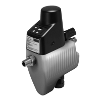
The power supply of the device is prepared by the factory:
• Power unit for wall socket.
• Plug for jack socket.
The electric wiring must be carried out by an electrician in accordance with all
applicable national and local regulations.
A socket with a power supply of 230 volts for the connection must be provided
by the customer.
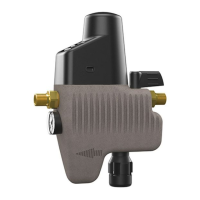
6.5.1 Terminal diagram
Assignment (from left to right)
Potential-free alarm
signalling contact for
forwarding of alarms to a
building control system /
Terminal 3-pole
• Connecting bridge (in normal
operation, bridge between 1+2,
in fault between 2+3)
• Root
• Changeover switch to reverse the
function of the switches 1+2
Pressure sensor - PH
connector 3 pole
• Pressure sensor supply
• Pressure sensor earth
• Pressure sensor signal
Motor,
Micro switch,
Battery - PH connector 6-
pole
• Battery + pole
• Battery earth
• Motor earth
• Motor supply
• Micro switch
• Micro switch
Pressure sensor - PH
connector 3 pole
• Pressure sensor supply
• Pressure sensor earth
• Pressure sensor signal
Assignment (from left to right)
Plug terminal of the
integrated motorised ball
valve
Note!
Confirm that installation and start-up have been carried out correctly
using the installation and commissioning certificate. This action is a
prerequisite for the making of warranty claims.
– Have the Reflex Customer Service carry out commissioning and
the annual maintenance.
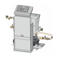
7.1 Requirements for initial commissioning
• The device is installed.
• The connections to the system circuit and the mains water system are
made
• All shut-off devices to the system circuit and the mains water system are
provided.
• The electrical connection has been created according to applicable
national and local regulations.
• The pipelines to the device are purged and free of dirt and welding residue.
• The connection of the drain funnel to the waste water system is made
according to the applicable DIN EN 12056 standard.
• The provided pressure gauge is installed at the pressure reducer.
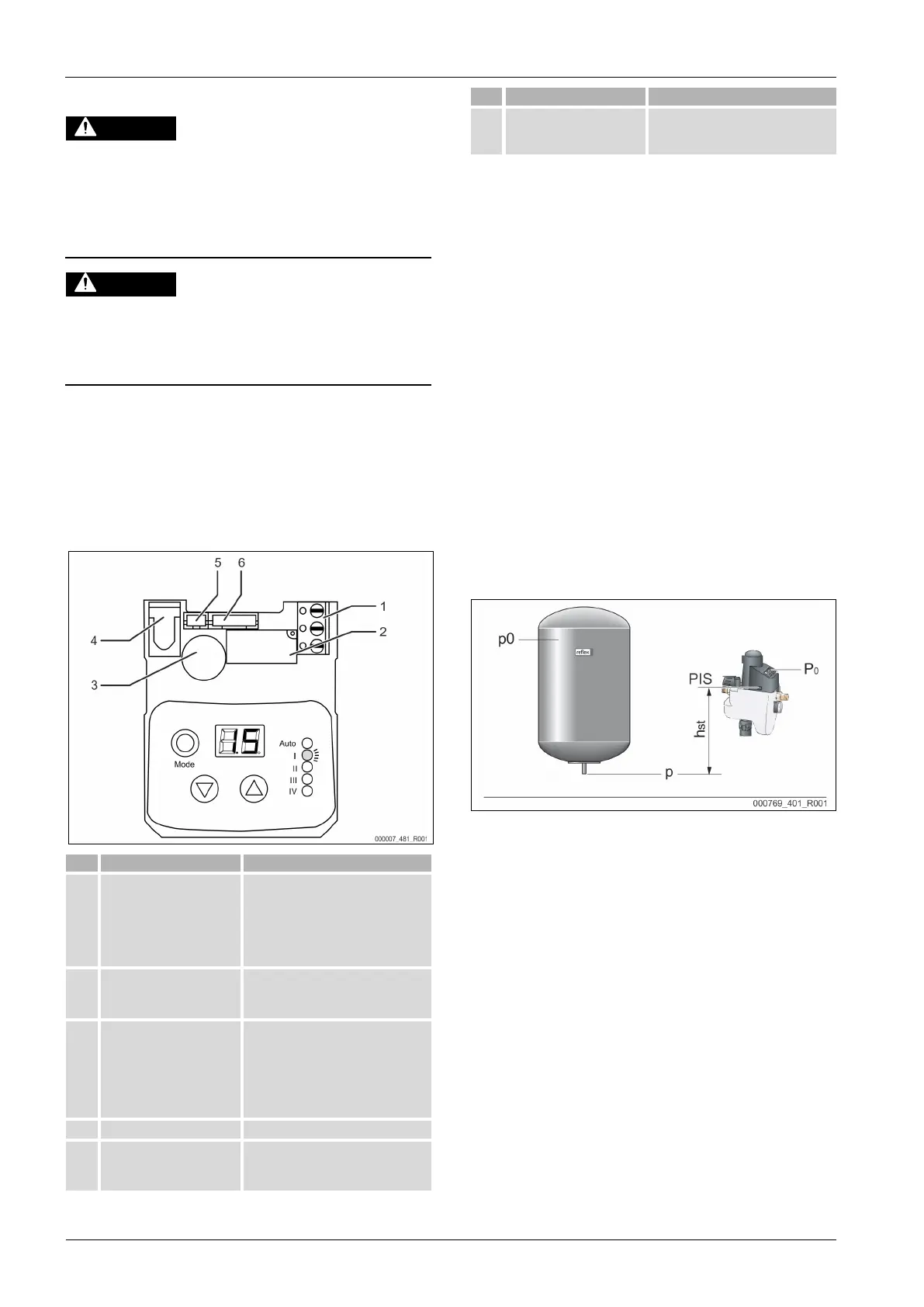
7.2 Determining the P
0
minimum operating pressure for the
controller
The "P
0
" minimum working pressure for the device is used in system circuits with
a diaphragm expansion vessel.
Calculate the "P
0
" minimum working pressure for the device:
• The device is installed at the same level (h
st
= 0) as the diaphragm
expansion vessel:
P
0
= p0
• The device is installed at a lower level than the diaphragm expansion
vessel:
P
0
= p0 + h
st
/ 10
• The device is installed at a higher level than the diaphragm expansion
vessel:
P
0
= p0 - h
st
/ 10
P
0
Minimum working pressure in bar
p0 Initial pressure, diaphragm expansion vessel, in bar
h
st
Static elevation in m
Note!
Calculate the filling pressure for the make-up with mains water into the
system circuit as follows:
Filling pressure ≥ P
0
+ 0.3 bar
Note!
During planning, take into account that the working range of the
device must be between the "PA" initial pressure and the "PE" final
pressure in the pressurisation working range.
 Loading...