8
System inställningar/
System-dependent setting
p
SV
[bar] =
Säkerhets upphämtning av trycket i värme generatorn/
Safety pick-up pressure at the heat generator
p
max
[bar] = 0.3 bar
≥ 0.5 bar
p
e
[bar] =
Slutnings tryck av expansionkärl/
Final pressure of the expansion vessel
p
a
=
vatten tillförsel när trycket understiger det önskade värdet/
Water make-up when pressure remains under below the required value
p
a
[bar] =
Fyllnings tryck p
F
av expansionskärlet/
Starting or lling pressure p
F
of the expansion vessel
p
0
[bar] = p
statisk/static
+ p
Avdunstning/evaporation
+ 0.2 bar (rekomenderas/recommended) ≥ 0.3 bar
p
st
[bar] =
Statiskt tryck (statisk höjd [m] / 10)/
static pressure (static height [m] / 10)
0...0.2 bar
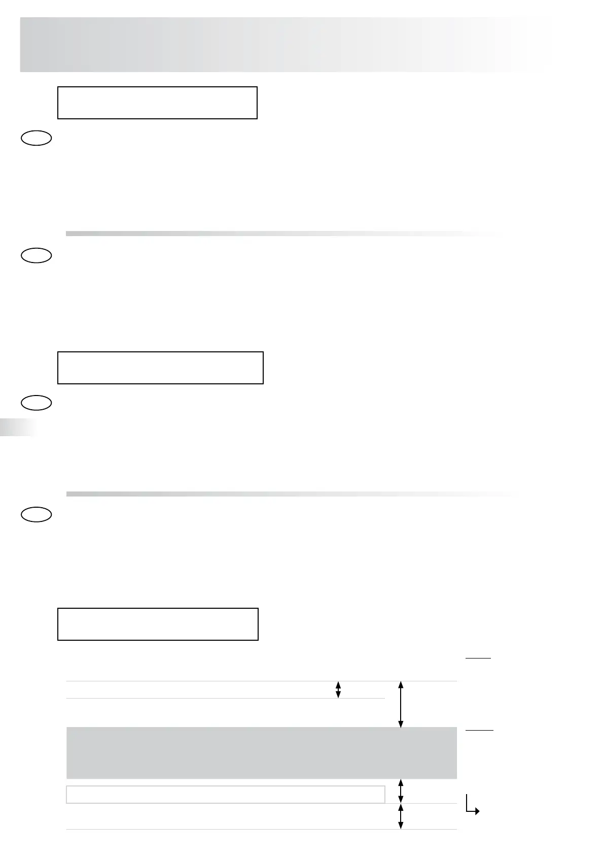
Exempel:
Värmesystemet,
statisk höjd 10 m
(p
st
= 1.0 bar),
p
0
= 1.0 bar + 0 bar + 0.2 bar
(rekomenderas)
p
0
= 1.2 bar
→ Vid igång körning
Example:
Heating system,
static height 10 m
(p
st
= 1.0 bar),
p
0
= 1.0 bar + 0 bar + 0.2 bar
(recommended)
p
0
= 1.2 bar → On-site setting
påfyllningsstation PÅ
= p
0
+ 0.1 bar = 1.3 bar
påfyllningsstation AV
= p
0
+ 0.3 bar = 1.5 bar
Förutsättningar för igångkörning/
Prerequisites for initial start-up
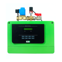
• Installationen av Reflex påfyllningsstation är nu klar.
• Inkopplingen på vattensidan av systemet inkl. uppströms och nedströms avstängningsventiler
sitter på plats.
• Elkopplingen enligt bestämmelserna VDE och EVU har blivit utförda.
• Rörledningarna till Reflex påfyllningsstation måste sköljas och rensas från smuts och svetsrester.
• Kopplingen av avtappningen till avloppet ska följa bestämmelserna enligt DIN EN 12056
• Manometern har blivit installerad på reduceringsventilen. (fabriks monterad från approx 06/06)
• Installation reflex ’fillcontrol’ is completed.
• The connection on the water side of the system and to the refill water incl. upstream and downstream shut-off
valves on-site is made.
• The electrical connection acc. to the valid VDE and the local EVU regulations has been established.
• The pipelines towards reflex ’fillcontrol’ have to be rinsed and to be cleaned from dirt and welding residue.
• The connection of the tundish to the sewage has to be made acc. to the valid norm DIN EN 12056.
• The enclosed manometer has been installed at the pressure reducer (from approx. 06/06 factory-mounted).
S
GB
S
Förberedelser igångkörning/
Steps to intial start-up
Vattenkoppling
Öppna alla avstängningsventiler för att ställa in kontroll parametrarna.
Parametrarna skall vara inställda efter kundens behov
Kontroll enheten inkluderar tre nivåer, och lösenord för att skydda service menyn (→ S. 11),
Meny för fyllning av systemet (→ S.10), och kundens inställda meny. Igångkörningen kan kräva vissa
justeringar av de fabriksinställda värdena beroende på vilket system den installeras i.
Establish water connection
Open all upstream and downstream shut-off valves prior to setting the control parameters.
System-dependent parameter setting of the customer menu
The control unit includes three control levels, the password protected service menu (→ p. 11), the menu for the
initial filling of the system (→ p.10), and the customer menu.
The initial start-up possibly requires the adjustment of some factory settings to the respective system-specific con-
ditions.
GB
reflex ’påfyllningsstation’
Förberedelse igångkörning/Initial start-up
 Loading...