Renesas RA Microcontrollers EK-RA4M1 v1 – User's Manual
R20UT4579EU0100 Rev.1.00 Page 12 of 32
Oct.02.19
5.2.2 Powering up the Board
When powered, the green LED to the right of the DEVICE USB connector (LED2) lights up.
The red LED in the same LED package functions as a status indicator for the J-Link
®
On-board (OB) debug
interface on the board. If both LEDs in the LED2 package are lit, LED2 appears orange.
Figure 11. LED2 on the Evaluation Kit Board (Top Side)
5.2.3 Battery Supply Configuration
An external battery may be connected according to the methods outlined in section 5.2.1, Power Supply
Options, providing that it meets the minimum voltage and current requirements.
Additionally, an external battery source may be connected to VBAT at Pin Header location J2-29 (J2-12
ground return) to maintain the MCU Realtime Clock (RTC) when other main power sources are disconnected
from the EK-RA4M1 board.
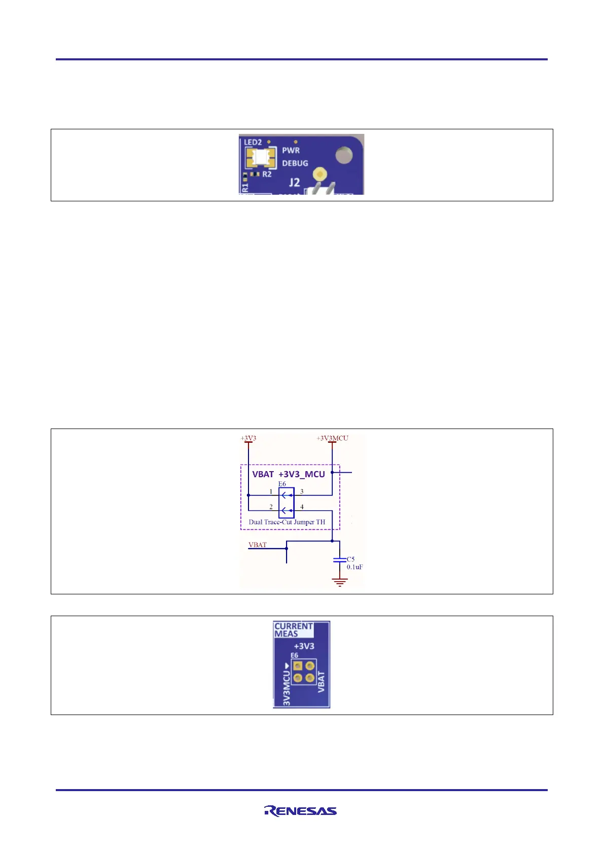
5.2.4 Measuring Current Consumption
Pads 1 and 3 of the copper jumper E6, which is a dual trace-cut jumper, allow measurement of +3V3 MCU
supply current. Pads 2 and 4 of E6 allow measurement of VBAT supply current. Both traces are connected
by default. These traces should be cut to enable power measurement. Care must be taken when cutting the
trace to not cause damage to PCB layers below the trace.
The actual current consumed by the RA4M1 MCU is dependent on many factors, including ambient
temperature, internal clock speed, input voltage level, and device activity. The actual current consumed by
the MCU can vary from less than 1 mA to nearly 40 mA. See the RA4M1 Microcontroller Group User’s
Manual for more information on the electrical characteristics of the MCU.
Figure 12. MCU Current Measurement Circuit
Figure 13. E6 on the Evaluation Kit Board (Top side)

 Loading...


