EasyManuals Logo
Home>Renesas>Motherboard>EK-RA4E2

Renesas EK-RA4E2 User Manual

Renesas EK-RA4E2
38 pages
To Next Page IconTo Next Page
To Previous Page IconTo Previous Page
Page #30 background imageLoading...
Page #30 background image
Renesas RA Microcontrollers EK-RA4M1 v1 – User's Manual
R20UT4579EU0100 Rev.1.00 Page 27 of 32
Oct.02.19
Figure 27. User Potentiometer on the Evaluation Kit Board (top)
5.6.4 Boot Configuration
The BOOT CONFIG jumper, J8 is used to configure the operating mode of the RA4M1 MCU at boot.
Table 17. Boot Configuration
Boot Configuration
J8 Shunt Location
Normal Boot (default)
Pins 1 and 2
SCI / USB Boot
Pins 1 and 3
Figure 28. Boot Configuration Jumper J8
5.6.5 Miscellaneous Signals
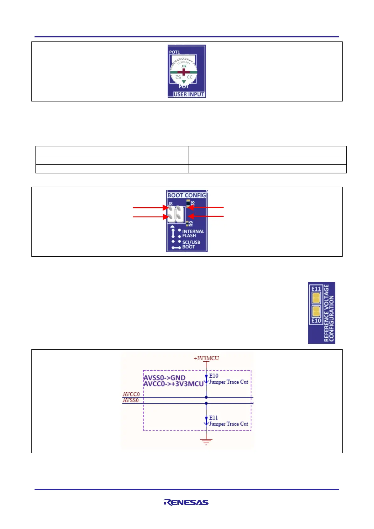
5.6.5.1 AVCC0/AVSS0
By default, AVCC0 is connected to +3V3 MCU and AVSS0 is connected to the system ground.
To disconnect these references from the AVCC0 and AVSS0 lines, copper jumpers E10 and
E11 must be open.
Figure 29. Analog and Reference Voltages
Pin 3
Pin 1
Pin 4
Pin 2

Other manuals for Renesas EK-RA4E2

Questions and Answers:

Question and Answer IconNeed help?

Do you have a question about the Renesas EK-RA4E2 and is the answer not in the manual?

Renesas EK-RA4E2 Specifications

General IconGeneral
BrandRenesas
ModelEK-RA4E2
CategoryMotherboard
LanguageEnglish

Related product manuals