Renesas VUI Reference Solution VOICE-RA4E1 Engineering Manual
VOICE-RA4E1 Engineering Manual Rev.1.0 Page
of 14
June 2022
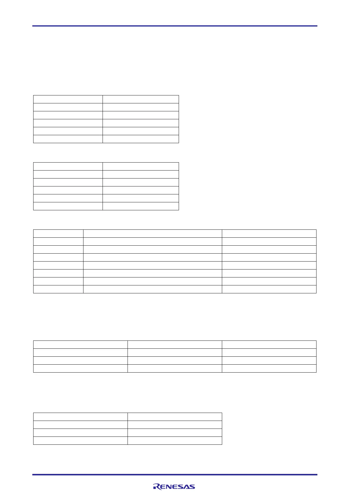
8.3 Microphones
This board includes a pair of analog MEMS microphones (M2 & M3, ZillTek ZTS6053). These 2 analog
microphone signals are amplified by Renesas READ2302GSP OPAMP, then fed to RA4E1 ADC channels 0
& 1. One digital I2S MEMS microphone (M1, ZillTek ZTS6672) is also provided, which is connected to
RA4E1 SPI0 channels. The physical distance between each 2 microphones is 50mm to support
beamforming applications.
Table 6. Analog MEMS Microphone left channel (M2) Port Assignments
Table 7. Analog MEMS Microphone right channel (M3) Port Assignments
Table 8. Digital I2S MEMS Microphone left channel (M1) Port Assignments
GND – for Select as left channel
8.4 Audio out
A stereo headphone jack is connected to the MCU DAC. The DAC signals are connected through an
OPAMP. The device is Renesas READ2302GSP, in ultra-small 8 pins TSSOP packages.
Table 9. Headphone Jack Pin Assignments
8.5 LEDs
3 LED are included on the board and are connected to the MCU I/O. These are Red, Green, and Blue, and
can be used for any user defined functions.
Table 10. User LED Port Assignments
D5 (blue) is power LED, and D8 (Green) is debug status LED to indicate the status of the JLOB connection.

 Loading...


