Renesas RA Microcontrollers EK-RA4M1 v1 – User's Manual
R20UT4579EU0100 Rev.1.00 Page 17 of 32
Oct.02.19
5.4.4 LEDs
Two LEDs are provided on the EK-RA4M1 board. U1 is the Main MCU, and directly controls LED1. See
Figure 8 for LED1 location and Figure 15 for the LED1 circuit. U2 is the J-Link MCU and controls the red LED
in LED2. See Figure 11 for the LED2 location, and Figure 10 for the LED2 circuit.
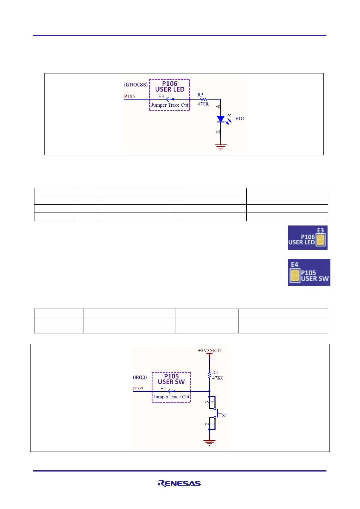
Figure 15. LED1 Control Circuit
The behavior of the LEDs is described in the following table.
Table 7. LED Functions on the Evaluation Kit Board
To disconnect the User LED from the MCU signal P106, the copper jumper E3 must be
open.
5.4.5 Switches
Two miniature, momentary, mechanical push-button type SMT switches are mounted on the
board. Pressing the RESET Switch generates a reset signal to restart the Main MCU.
To disconnect the User Switch from the MCU signal P105/IRQ0, copper jumper E4 must be
open.
Table 8. Switches on the Evaluation Kit Board
Figure 16. User Switch Circuit
 Loading...


