EasyManuals Logo
Home>Renesas>Motherboard>RA4M2

Renesas RA4M2 User Manual

Renesas RA4M2
38 pages
To Next Page IconTo Next Page
To Previous Page IconTo Previous Page
Page #21 background imageLoading...
Page #21 background image
Renesas RA Microcontrollers EK-RA4M1 v1 – User's Manual
R20UT4579EU0100 Rev.1.00 Page 18 of 32
Oct.02.19
Figure 17. User Switch (S1) on the Evaluation Kit Board
Figure 18. Reset Switch Circuit
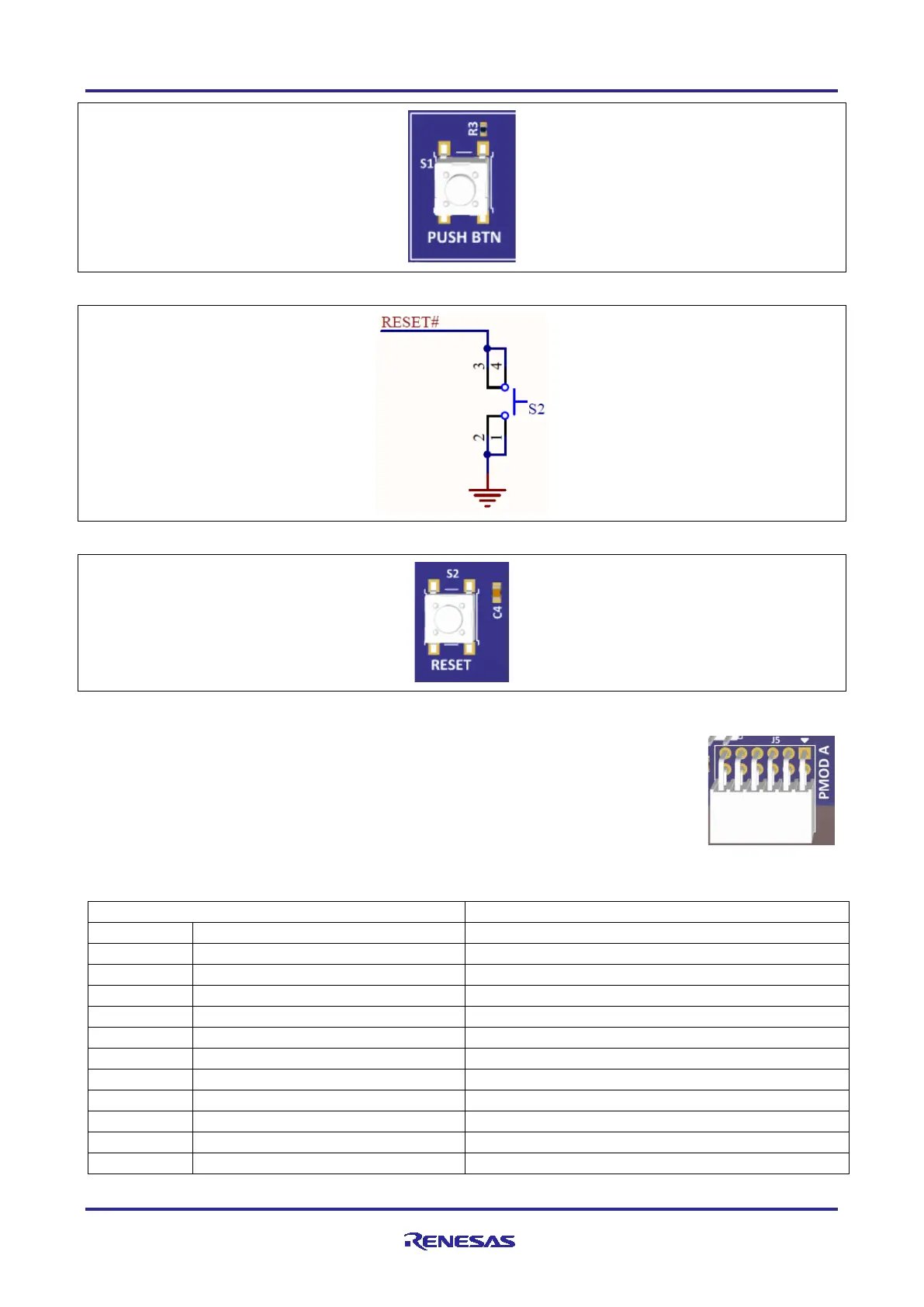
Figure 19. Reset Switch (S2) on the Evaluation Kit Board
5.4.6 PMOD A
A 12-pin PMOD type 2A connector is provided at PMOD A. The interface is powered for
3.3 V modules only. The Main MCU acts as the SPI master, and the connected module
acts as an SPI slave device. This interface may additionally be re-configured in firmware
as several other PMOD types.
Signals on PMOD A are shared with Main MCU pin headers J1 and J2. Care must be
taken to ensure that shared signals are not used concurrently.
Table 9. PMOD A Connector (J5)
PMOD A Connector
EK-RA4M1
Pin
Description
Signal/Bus
1
SS (low to select slave)
U1 P103, SSLA0_A (U1-72)
2
MOSI
U1 P101, MOSIA_A (U1-74)
3
MISO
U1 P100, MISOA_A (U1-75)
4
SCK
U1 P102, RSPCKA_A (U1-73)
5
GND
GND
6
VCC
+3V3
7
INT (slave to master)
U1 P104, IRQ1 (U1-71)
8
RESET (master to slave)
U1 P107, GPIO (U1-68)
9
Not Specified
U1 P111, GPIO (U1-54)
10
Not Specified
U1 P112, GPIO (U1-55)
11
GND
GND

Other manuals for Renesas RA4M2

Questions and Answers:

Question and Answer IconNeed help?

Do you have a question about the Renesas RA4M2 and is the answer not in the manual?

Renesas RA4M2 Specifications

General IconGeneral
BrandRenesas
ModelRA4M2
CategoryMotherboard
LanguageEnglish

Related product manuals