Board Description
This chapter will explain the functions of the board in detail. The figure below
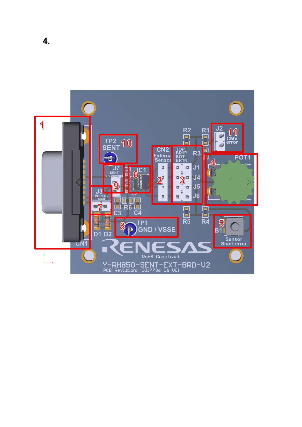
shows an overview of the board. To provide a better explanation to the user the
different functional groups are highlighted with numbers which are mentioned in
the following sub chapters.
Figure 3: RH850 SENT Application Board with Functional Groups
4.1 Connectors
The board offers the following connectors to the user.
4.1.1 Main Connector CN1 [1]
This is the main connector for the board. The power supply and SENT bus line
will be provided via this DB9 connector.
4.1.2 External Sensor Connector [2]
The connector is used when you want to connect an external sensor circuit to the
board. Make sure that the built-in sensor circuit is disconnected by the “Board
Sensor Disconnect” jumpers [3] when using an external sensor.

 Loading...