RL78/G1D RL78/G1D Solution Kit – PMOD Module Hardware Manual
R01AN2919EU0100_RL78G1D Rev. 1.00 Page 4 of 4
Sept. 15, 2015
2. RL78/G1D-SK PMOD module interface
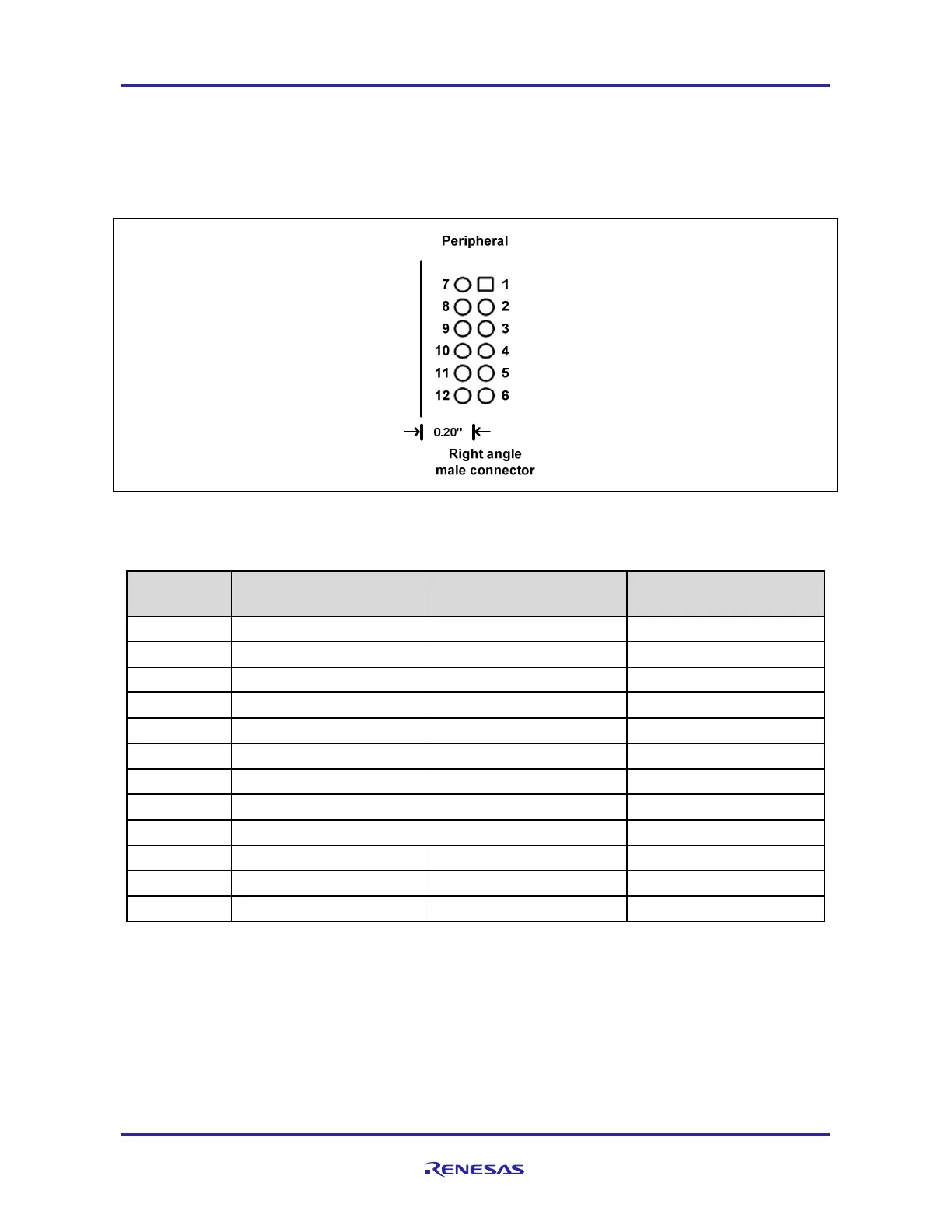
For interface connection, the RL78/G1D-SK PMOD module has 2x6 pin, standard 0.1-inch pitch right angle male
connector. Using this connector, you can program or debug RL78/G1D-SK Bluetooth
®
module. If you program
firmware in Modem configuration, the module can be used for Bluetooth
®
communication
by plugging into one of the
PMOD connectors on the Renesas RDK board like YRDKRL78-G14. The PMOD connector pin number and pin
orientation are shown in Figure 2, and Table 2 shows the pin configuration.
Figure 2 PMOD connector pin assignment for RL78/G1D-SK PMOD module
Table 2 Interface between Host and Peripheral PMOD
Number
(Host)
(Peripheral)
PMOD Signal
1 PMOD-WAKEUP P30 PMOD_CS
2 PMOD-TxD P11 (RxD0/SI00) PMOD_MOSI
3 PMOD-RxD P12 (TxD0/SO00) PMOD_MISO
4 PMOD-SCK P10 (SCK00) PMOD-SCK
5 GND GND GND
6 VDD (3.3 V) VDD (via R1 and R4) VDD
7 PMOD-SDIR (INTP) P21 PMOD_PIN7
8 PMOD-GPIO nRESET PMOD_PIN8
9 PMOD-GPIO P16 PMOD_PIN9
10 PMOD-GPIO TOOL0 PMOD_PIN10
11 GND GND GND
12 VDD (3.3 V) VDD (via R1 and R4) VDD
The PMOD connector has flexible interface to communicate either UART or CSI mode. The RL78/G1D-SK PMOD
module can support five communication modes based on programmed firmware as below. Refer document
R01UW0095EJ0117 [2] for detail.
2-Wire UART
3-Wire UART
2-Wire UART with branch
4-Wire CSI
5-Wire CSI

 Loading...


