RL78/G1D RL78/G1D Solution Kit – PMOD Module Hardware Manual
R01AN2919EU0100_RL78G1D Rev. 1.00 Page 5 of 4
Sept. 15, 2015
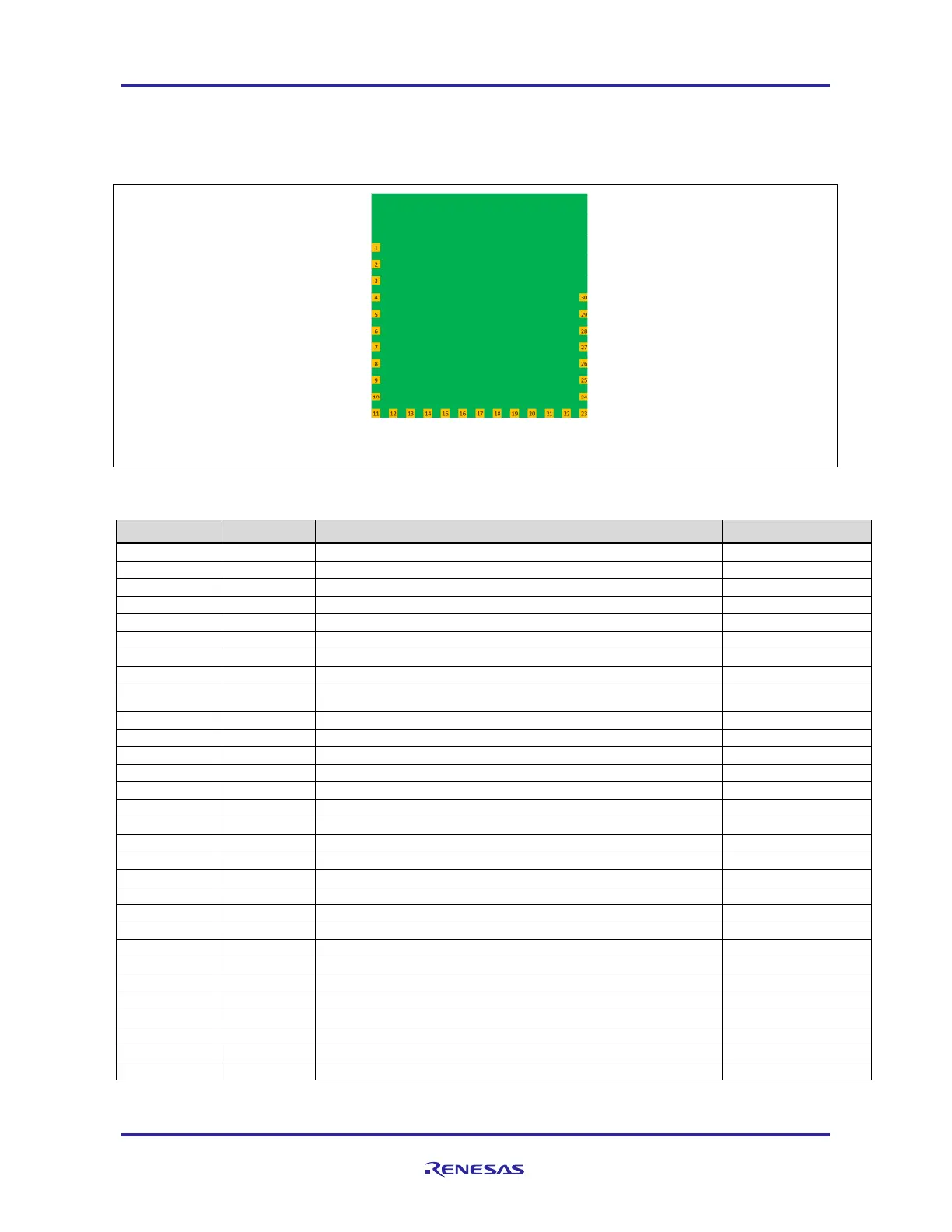
3. RL78/G1D-SK Bluetooth module Pin Configuration
After breaking away the PMOD connector of the PMOD module, you get Bluetooth
®
module, with dimensions
12.7x12.7 mm (½ inch square). The module has 30 gold plated pads at bottom layer and their respective functions are
described in Table 3 . Refer MCU device detail in RL78/G1D User’s Manual: Hardware, R01UH0515EJ0100 [1].
P147
P23
P22
P21
P20
P03
P02
P01
P00
VDD_IO
nRESET
TOOL0
GND
GND
VDD_RF
P30
P16
P15
P14
P13
P12
P11
P10
GPIO0
GPIO1
P61
P60
P137
P121
P120
BOTTOM VIEW
Figure 3 RL78/G1D-SK module pin configuration
Table 3 RL78/G1D-SK module Pin Function
Pin Number Designator
Description Remark
1 GND Ground
2 VDD_RF RF +3.0 volt power supply
3 P30 GPIO/External Interrupt Input 3 / Real-time clock (1 Hz) Output
4 P16 GPIO/ Timer01 Input, Output / External Interrupt Input 5
5 P15 GPIO/ CSI20 clock/ I
C 20 clock Output/ Timer02 Input, Output I
C 20: Simplified I
C
6 P14 GPIO/ CSI20 Input/ I
C 20 Data/IIC0A clock Output/ Timer03 Input, Output I
C 20: Simplified I
C
7 P13 GPIO/ CSI20 Output/ I
C 0A Data/ Timer04 Input, Output
8 P12 GPIO/ CSI00 Output / UART 0 Transmit Output / Timer05 Input, Output
9 P11 GPIO/ CSI00 Input/ UART 0 Receive Input/ I
C00 Data/ Timer06 Input,
Output
10 P10 GPIO/ CSI00 clock / I
C00 clock Output / Timer07 Input, Output
11 P147 GPIO/ Analog Input 18
12 P23 GPIO/ Analog Input 3
13 P22 GPIO/ Analog Input 2
14 P21 GPIO/ Analog Input 1/ Analog Reference Minus
15 P20 GPIO/ Analog Input 0/ Analog Reference Plus
16 P03 GPIO/ Analog Input 16/ UART 1 Receive Input
17 P02 GPIO/ Analog Input 17/ UART 1 Transmit Output
18 P01 GPIO/ Timer00 Input
19 P00 GPIO/ Timer00 Output
20 VDD_IO MCU +3.0 volt power supply
21 nRESET Reset Input
22 TOOL0 General purpose Input/ Debug, Programming
23 GND Ground
24 P120 GPIO/ Analog Input 19
25 P121 General purpose Input Input only
26 P137 GPIO/ External Interrupt Input 0
27 P60 GPIO/ I
C 0A clock Output
28 P61 GPIO/ I
C 0A Data
29 PGPIO1 RF transmission output for external power amplifier control Active High
30 PGPIO0 RF transmission output for external power amplifier control Active Low
Note: General Purpose Input Output (GPIO)

 Loading...


