RL78/G13 Safety Function (Frequency Detection)
R01AN0956EJ0100 Rev. 1.00 Page 12 of 70
Feb. 27, 2012
5.4 List of Constants
Table 5.3 lists the constants that are used in this sample program.
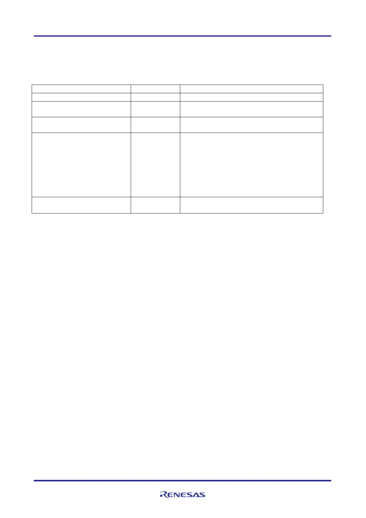
Table 5.3 Constants for Sample Program
Constant Setting Description
_0001_TAU_OVERFLOW_OCCURS 0x0001U Overflow occurrence detection
PULSEWIDTH_RANGE_MIN 1836
Lower limit of the tolerable range for pulse interval
measurement
PULSEWIDTH_RANGE_MAX 2535
Upper limit of the tolerable range for pulse interval
measurement
TAU0_COUNT_CLOCK_1 0x00 Count clock 1 for TAU0.
It is predefined as one of these values:
0x00: 32 MHz
0x01: 16 MHz
0x02: 8 MHz
0x03: 4 MHz
0x04: 2 MHz
0x05: 1 MHz
TAU0_COUNT_CLOCK_2 0x01 Count clock 2 for TAU0.
Same as TAU0_COUNTCLOCK_1.
Note 1: The above PULSEWIDTH_RANGE_MIN and PULSEWIDTH_RANGE_MAX are calculated as follows.
PULSEWIDTH_RANGE_MIN = HOCO_FREQUENCY_MIN / LOCO_FREQUENCY_MAX
PULSEWIDTH_RANGE_MAX = HOCO_FREQUENCY_MAX / LOCO_FREQUENCY_MIN
HOCO_FREQUENCY_MIN: Value (31.68 MHz) calculated by considering a tolerance of
the HOCO frequency (–1 %)
LOCO_FREQUENCY_MAX: Value (17.25 KHz) calculated by considering a tolerance of
the low-speed on-chip oscillator frequency (+15 %)
HOCO_FREQUENCY_MAX: Value (32.32 MHz) calculated by considering a tolerance of
the HOCO frequency (+1 %)
LOCO_FREQUENCY_MIN: Value (12.75 KHz) calculated by considering a tolerance of
the low-speed on-chip oscillator frequency (-15 %)
Change the upper and lower limits of the tolerable range for pulse interval measurement depending on the
system used.

 Loading...


