RL78/G13 Safety Function (Frequency Detection)
5.8.9 Main Processing
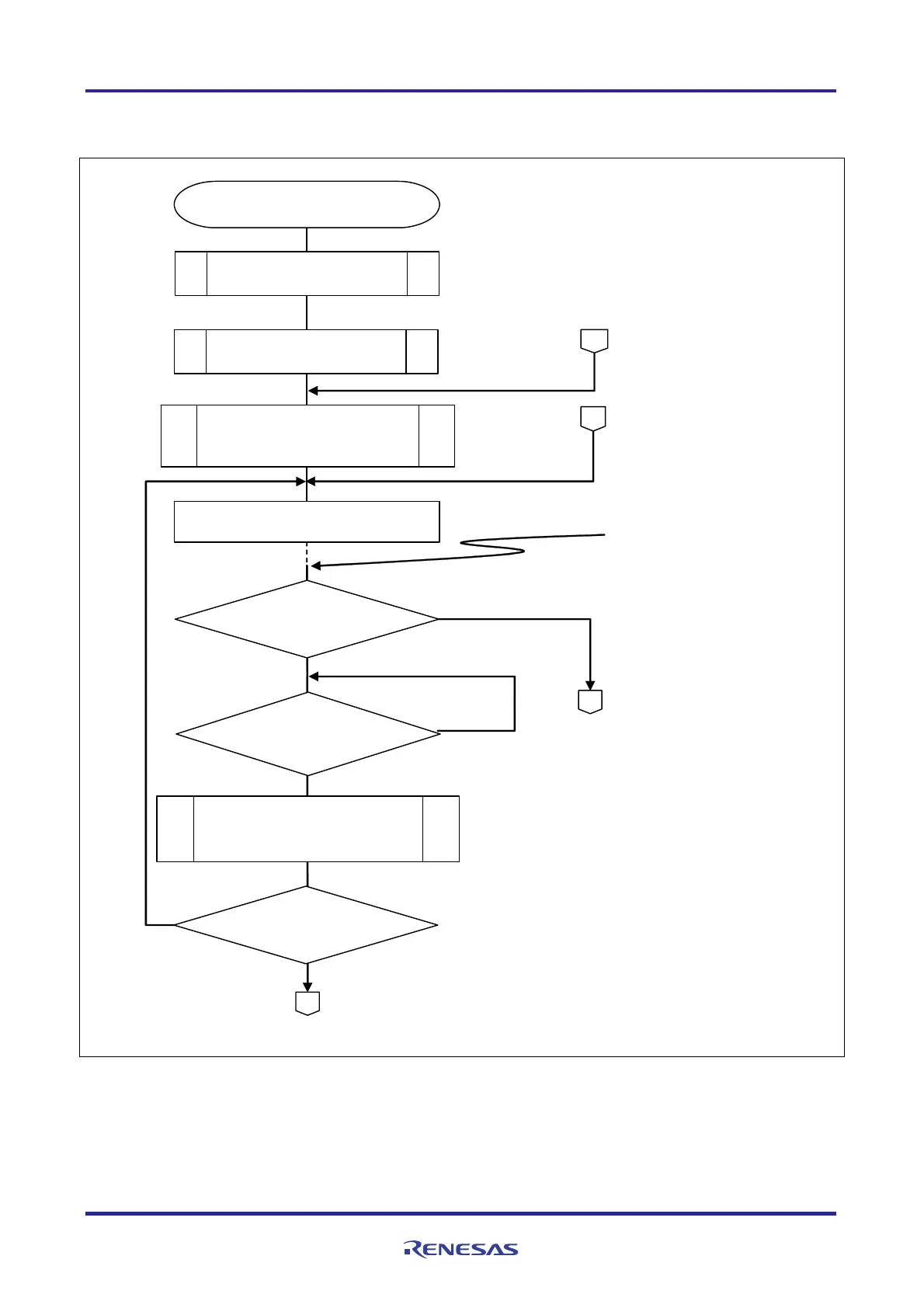
Figure 5.10 shows the flowchart for the main processing.
Start pulse interval measurement
R_TAU0_Channel5_
MeasureStart()
main()
Start INTP0 operation
R_INTC0_Start()
Change to HALT mode
Pulse interval
measurement end or
switch depression
detection
If switch depression is
detected, start interval
timer.
Set interval timer interrupt
flag to 1 upon interval
timer interrupt.
Check P137 status. If it is
0, determine that switch
has been depressed.
Then, set count clock
change request flag to 1.
No
Switch depression
detected?
Ye s
No
Interval timer
interrupt generated?
Obtain count clock change
request flag
R_IT_Get_fCLK_ChangeFlag()
D
C
Ye s
Set HOCO clock
R_Main_HOCO_Change()
Specify HOCO clock as a constant of count
clock 1 (TAU0_COUNT_CLOCK_1).
B
Count clock change
requested?
Ye s
No
Figure 5.10 Main Processing (1/3)
R01AN0956EJ0100 Rev. 1.00 Page 38 of 70
Feb. 27, 2012

 Loading...


