RZ/T2M Group RZ/T2M Motor Solution Board Hardware Manual
R01AN5986EJ0100 Rev.1.00 Page 27 of 30
Jul.31.21
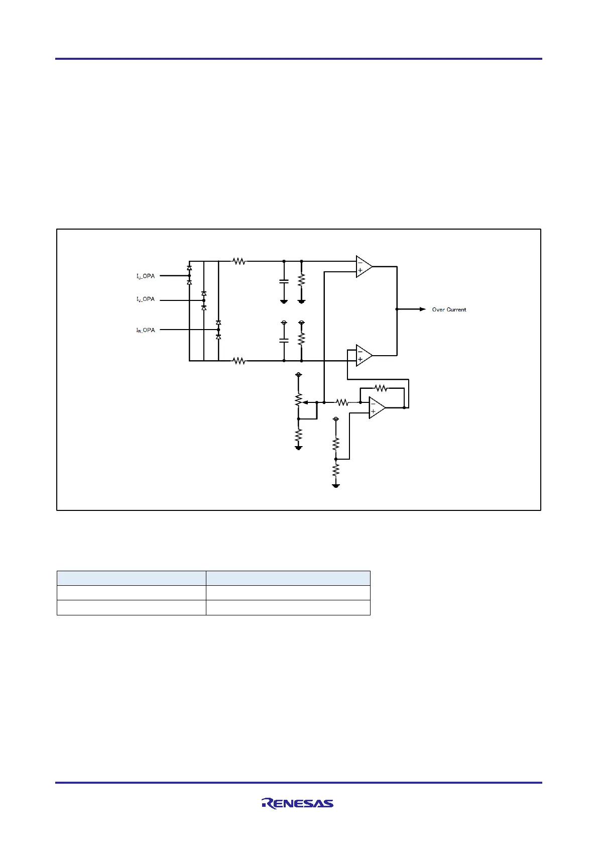
5.1 Overcurrent detection circuit
The overcurrent detection circuit in Figure 5.1 is used to detect overcurrent from the shunt resistance of each
of the U, V, and W phases.
The overcurrent detection circuit determines that the current is overcurrent when any one of the currents
flowing in the U, V, and W phases exceeds the threshold value.
The threshold is determined by the volume resistor VR1 and is set to full clockwise in the initial state.
Table 5.2 is shown the relationship between the volume resistor VR1 and the overcurrent detection current
value. Adjust the volume resistor VR1 according to the application and set the threshold value.
If the current value is within the threshold range, the terminal POE_FOVx outputs High, and when an
overcurrent is detected, it outputs Low. You can protect the RZ / T2M motor board and motor by monitoring
terminal POE_FOVx and forcing the PWM output to go into the Hi-Z state when the output is low.
Figure 5.1 Outline of overcurrent detection circuit
Table 5.2 Volume resistor VR1 and overcurrent detection current value
Volume resistance value [Ω]
Overcurrent detection current value [A]
10k(Full counterclockwise)
Shunt resistance
(Via amplifier)
POE_FOVx
Volume resistance
VR1
 Loading...


