EasyManua.ls Logo

Revox B260 User Manual

Revox B260
110 pages
Go to English
To Next Page IconTo Next Page
To Previous Page IconTo Previous Page
Page #64 background image
Technical appendix SCOPE
outputs
Multipath reception
scoPE
[36]
good
Analog signal
meter
o@
@
8lo
o
o
Multipath reception occurs
when in addition
to
the direct
signal
from the transmitter
an-
tenna of
a
given
station,
signals
reflected from
building walls or
mountains are also
received.
The different delays between
these two si-
gnals
can
produce
undesirable
distortions
that cannot be corrected
even by the best
re-
ceiver.
Although the
REVOX 8260-5
'
tuner offers
maximum
immunity against such
pheno-
mena, the only effective
remedy
in many
cases is to
relocate
the
antenna to
a different
position.
The true
quality
of the
received signal
can be
measured
on
the SCOPE
[36]
sockets.
A cathode
ray
oscilloscope
(with
external
X-
input) can be connected
to the SCOPE
[36]
outputs
for displaying and analyzing
the
multi-
path
reception.
The illustrations on the left
are
showing
three
kinds
of delay distortions
as displayed
on an
oscilloscope screen.
Via the sockets SCOPE
[36]
frequency deviation and signal
strength
can be displayed. lf
you
wish to make
visible
the signal strength
as
well,
an oscilloscope
with DC-input is required.
lf
you prefer
an
analog signal
meter
(needle-
type instrument) for analyzing the
strength
of
the incoming
signal,
you
can connect
it to the
SCOPE Y
[36]
output.
A 1O0pA
instrument
should be used.
acceptable
-
devratron
bad
(distorlion
audible
vioient)
Signal
strength
Strong signal.
large
deviation
+
deviation
o
o@
@
8lo
o
o
--T\
+
Pi ot srgnal
9% on
stereo transmlsstons
27
Question and Answer IconNeed help?

Do you have a question about the Revox B260 and is the answer not in the manual?

Revox B260 Specifications

General IconGeneral
BrandRevox
ModelB260
CategoryTuner
LanguageEnglish

Summary

SECTION 1 Installation

Installation Procedure Overview

Contains the basic information for operating the tuner.

Start Up and Power On

Covers line voltage, connections, and power on procedures.

SECTION 2 Main Keypad

Main Keypad Functions Overview

Explains all main functions of the tuner.

Accessing Station Memories

How to access stored station frequencies and data.

Accessing Program Identification

Method to retrieve stations based on program type.

SECTION 3 Auxiliary Keypad

Auxiliary Keypad: Hinged Cover and Station Selection

Accessing auxiliary functions and selecting stations manually.

Auxiliary Keypad: Modifying Reception Parameters

Adjusting RF, IF, and other settings for optimal reception.

Auxiliary Keypad: Entering Station Abbreviations

How to assign custom names to station memories.

Auxiliary Keypad: Output and Station Level Adjustments

Setting audio output and station memory levels.

SECTION 4 Fault Sources

Fault Sources and Troubleshooting

Common issues and solutions for tuner operation.

Technical Appendix

IR Remote Control Operation

Operation of the unit via infrared remote control.

SCOPE Outputs and Signal Metering

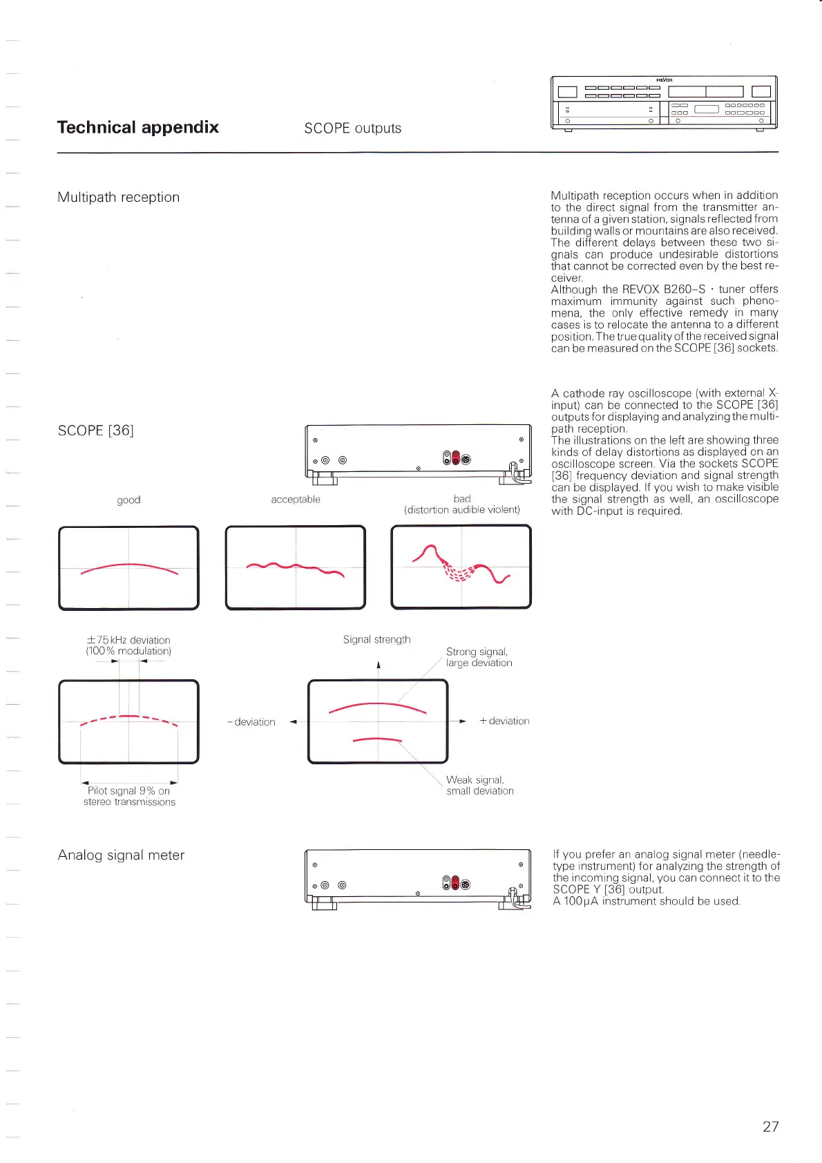
Using oscilloscopes and meters for signal analysis.

Unit Dimensions

Physical size specifications of the tuner.

Interesting Facts about RDS

Information on Radio Data System features and types.

Technical Data and Specifications

Detailed electrical and performance specifications.

SECTION 5 Index of Keypad Functions

Section 5: Keypad Functions Quick-Reference

Overview of all keypad functions and their pages.

Rear Panel Connections

Rear Panel: Antenna and Audio Connections

Details on connecting antennas and audio equipment.

Rear Panel: Serial Link and AC Power

Ports for external control and main power connection.

Synoptical Diagram

Related product manuals