To de-energize the solenoid and to restore the nonconducting condition, the supply
voltage has to be interrupted.
B. Mechanical end-of-tape switch.
This switch and its associate operating levers must be thoroughly clean to function
correctly. On G-36 recorders up to serial number 36 500, the tape sensing lever
operates a snap-action switch (SE schematic A) which is closed with tape tension
applied. The right position of the switch assembly is essential for correct operation to
be obtained. This adjustment is carried out by slackening the fixing screws and
moving the switch bodily until the snap-action switch closes when the sensing lever
still protrudes by 0.5 to 1 mm from the outer diameter of the tape guide.
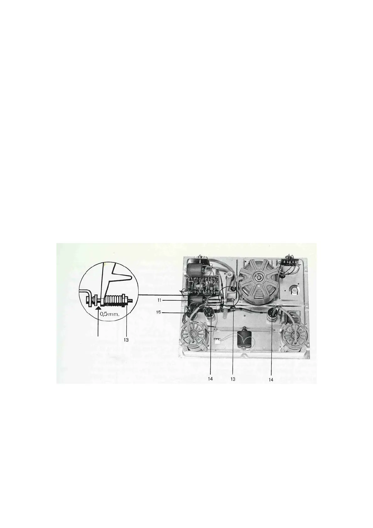
On recorders with serial number 36 500 and up, the sensing lever operates a gold-
plated wire contact. This switch opens when tape tension is applied (see BE in
schematic Band 7.736.001-002). Adjustment should be carried out analogue to the
above specifications for the snap-action switch by bending the long wire loop. In the
resting position sufficient contact pressure should be available to make the short wire
loop move beyond the point of contact by approx. 0.5 mm. This is achieved by
bending the contact wires while operating the tape sensing lever by hand.
The end-of-tape switch and its operating lever are then properly adjusted when the
switch remains open (or closed on older models) for any movement of the sensing
lever inside the tape-guide post. Accidental tripping due to sticky splices etc. will
thus be avoided.
2.1.6 Wow and flutter
 Loading...