77
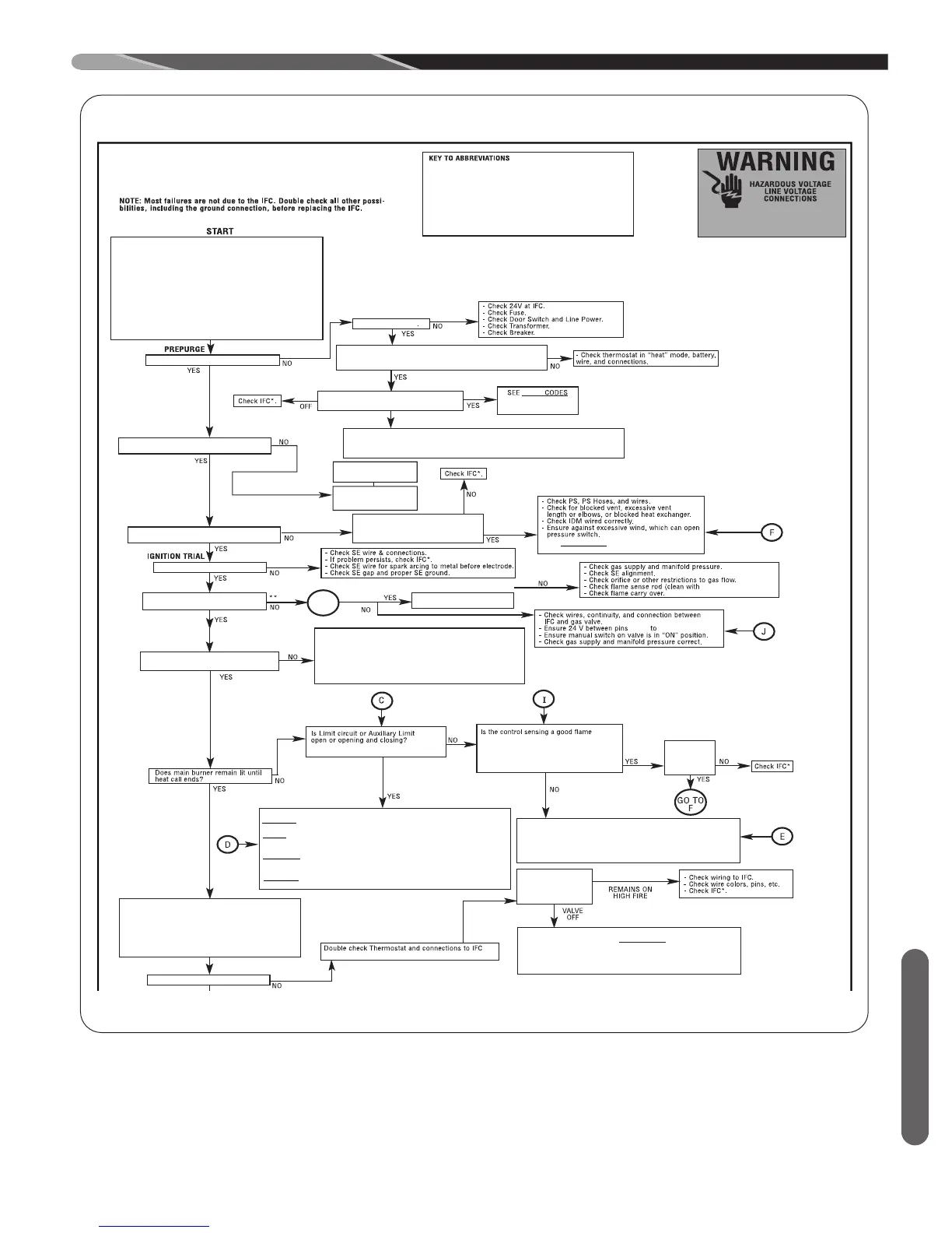
FIGURE 47
DIAGNOSTICS FLOWCHART
2-STAGE COMMUNICATING INTEGRATED
FURNACE CONTROL (IFC)
DIAGNOSTIC CHART
ECM = Constant CFM Blowers. (Electronically commutated motor)
TST AT = Thermostat.
IDM = Induced Draft Motor (or Inducer).
IFC = Integrated Furnace Control (or control board).
PS = Pressure Switch(es).
PFC = Power Factor Correction Choke.
SE = Spark Electrode (s).
SSD = Seven Segment Display of Furnace
control
COMM. = Communication.
I&O = Installation & Operation Instructions Manual.
1) For communicating systems, Remove communications
connections from the T-stat (E1, E2) and use a jumper wire
between R & W2 to set high stage gas heat. For legacy
systems ensure W2 & W1 are properly connected and make
sure both are energized w/ 240 AC after the heat call is placed.
2) Set FAN switch to “AUTO” on T-stat.
3) Set thermostat to call for heat (set temp. differential to greater
than 10°F). (Comm. jumper W1 to R and W2 to R)
4) “H” should
be displayed at “SSD’s” and should be on steady, if
flashing check dip switches (Item “1”).
IS
“A Lower case H is displayed at IFC SSD’S” ?
Dual SSD’S “ON” ?
Is thermostat heat call present?
For 24 VAC (Non-Comm. T-stat., is 24 VA C on W1 and/or W2 of
IFC. H or h should be displayed at SSD’S. ?
Is a faul
t code displayed at IFC?
(After 10 Sec. a fault code will display anyway)
H or h only
For 1st 10 Sec. only
FAULT
Under ”T roubleshooting”
in I & O Manual
Check W2 & connections,
replace or repair as
necessary
Check t-stat, replace if
necessary .
(pre-purge) IDM runs for 30 sec. at low speed?
Does IDM Run for 60 Sec. and then off
for five minutes with fault
45, 46 or 57 displayed?
- See F AULT CODES under
“T roubleshooting” in
I&O Manual.
ECM BLOWER “ON” DELAY
P2 - 6
P2 - 4 on IFC.
NOTE: If IFC goes into lockout, shut off main power to unit, wait 30
seconds then reset power or removed heat call and re-establish.
- Check a ll connections between I. F.C. & E. C.M. Motor.
- Check 24v to E.C .M. control (4pin connector, pin 1-4)
- Check Dip switch setting.
- Check P.F.C. choke. (if present)
- Check a ll wiring and connections to P.F.C choke.
- Check fau
lt code display, see “fault codes” in I & O. (if present)
- Check line vol tage to motor (115VAC).
Does ECM blower start on Low heat
speed 15-20 seconds after burners light?
Note: IFC SSD’s will display “22 or 33”.
?
Note: If good flame is not sensed a fault code
“1 1” or “13” will be displayed at SSD’s
Note: “12” is low
flame sense, furnace should
still operate well.
Fault code
“45”, “46” or
“57” displayed
at SSD’s.
CHECK:
- Fault codes at IFC SSD - see FAULT CODES under troubleshooting
in I&O manual.
- 24V Between IFC pins P2-5 & P2-4 of I .F.C.
- Make sure High heat call present at T-stat.
- T-stat wires and connections
Apply the 2nd stage heat call
while low heat call
remains. Ensure 24 VAC to W1 & to W2
A capital “ H” shoul d be displ ayed.
Be sure to note dip switch settings before troubleshooting.
Lower case “h”
Capital “H ”
-Check line voltage at I.D.M.
-Check Wires And connections between I.D.M. and I.F.C.
-Ensure line voltage between P3, Pin 2 & P3, Pin 3 of I.F.C. (High IND Output).
-Check I.D.M. Capacitor .
Spark Electrodes (SE) Energize
?
See I&O.
Does gas valve remain
energized?
PROBLEM
PERSISTS ?
CHECK:
AIRFLOW - ensure no restrictions, such as dirty filter, blower wheel ,
dampers or cl osed registers, Etc. exist.
LIMITS - ensure good wire and connections between I.F.C. and all limits.
makes sure limits are not open when circulating air temperature is within
a
specific range.
ROLLOUTS - Ensure rollouts or overtemperature limits do not need to be
reset. make sure no f lame rollout in burner compartment due to blocked f lue
or heat exchanger or combustion restriction.
OVERFIRE - ensure furnace is not overfired (temp rise is above stated
range). Check gas valve, proper orifice size, gas presure
CHECK:
-Grounding on I. F.C. in place and continuity between screw and field
-installed ground.
-Flame sense rod clean (cl ean if nessessary).
-Wire continunity between f lame sense rod and Pin P2-7 on I.F.C.
-Flame carries across all burners, and
all burners stay lit.
G0 T0
I
Does the IDM Start on Low Speed?
DISCONNECT POWER BEFORE SERVICING.
SERVICE MUST BE BY A TRAINED,
QUALIFIED SERVICE TECHNICIAN.
scotchbrite pad)
.
ST -A1194-66-00
Does Main Burner Light and stay lit
on Low?
STEADY LOW HIGH
LOW HEAT CALL END
Does Gas valve switch to High Fire?
Is gas valve
remaining on Low
or de-energizing
completely?
 Loading...