51
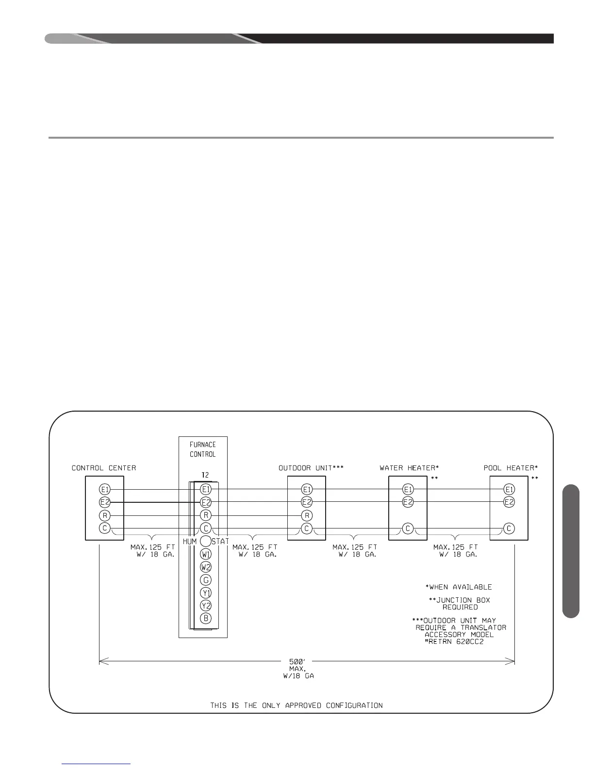
FIGURE 36
WIRING DIAGRAM FOR A FULLY COMMUNICATING SYSTEM.
ST-A1217-01
Communicating Furnace
INTEGRATED FURNACE CONTROL
THERMOSTAT WIRING DIAGRAMS-COMMUNICATING
18. THERMOSTAT INPUTS (T2) – THERMOSTAT
WIRING DIAGRAMS
Both communicating and legacy thermostats are to be
connected at terminal block T2.
A. COMMUNICATING SYSTEMS
The furnace is capable of communicating with a
thermostat and condenser to improve cooling and
heat-pump airflow, displaying active faults and ac-
tive furnace information at the thermostat and im-
proved diagnostics and troubleshooting.
WIRING A FURNACE FOR COMMUNICATIONS.
Maximum wire lengths and notes about wiring communi-
cating systemsare noted below.
MAXIMUM COMMUNICATING WIRE LENGTHS
(E1, E2, R & C)
Max Wire Length – Thermostat to Furnace = 125 FT @ 18 AWG*
Max Wire Length – Furnace to Condenser = 125 FT @ 18 AWG*
Max Wire Length – Between any 2 devices = 125 FT @ 18 AWG*
Sum Max Total Wire Length for All Components = 500 ft
(see Figure 36)
Notes:
1. Wires may be solid or stranded.
2. *Wire gage smaller than 18 AWG is not approved or
recommended for this application.
3. If the thermostat wiring will be located near or in paral-
lel with high voltage wiring, cable TV, Ethernet wiring,
or radio frequency equipment, then shielded thermo-
stat wire can be used to reduce or eliminate potential
interference. The shielding must be contiguous (have
continuity) across all devices and all wire segments.
This should be done by twisting the shielding wires
from adjacent segments together. Further, the shield-
ing for the entire system must be grounded in a single
location. Multiple grounds on the shielding system are
NOT permitted. The shield wire should be connected
to the C terminal, or ground, at the indoor unit. The
shield wire should NOT be connected to any terminal
at the Control Center (aka;Thermostat). Connecting
the shield to ground at both ends can cause current
loops in the shield, reducing shield effectiveness.
4. When using existing wire from a previous installation,
be sure to trim the tip of the wire back past the insula-
tion and strip a small amount of insulation from the
wire to expose clean new copper for the communicat-
ing connections. Fresh copper must be exposed when
making the communicating connections or communi-
cations may not be properly established.
A. WIRING OF FULLY COMMUNICATING SYSTEMS.
 Loading...