TM031 Integrity 18, 20, 24, 26L Service Instructions REV: B
D.O.I: February 2008
This document is stored and maintained electronically by Service. All printed copies not bearing this statement in RED are deemed “uncontrolled”
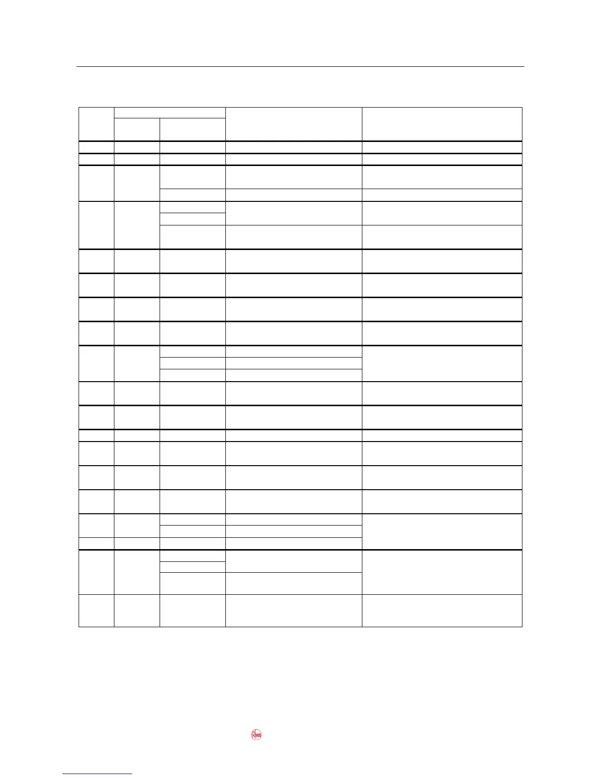
Diagnostic Test Points
Refer to wiring diagram, page 5, for connector and wiring positions.
50 kilo-ohms – 500 kilo-ohms
Water Flow Sensor pulse signal
Fan Motor is pulse signal
Heat Exchanger Thermistor
Hot Water Outlet Thermistor
Flame Sensor detecting flame
Proportional Gas Flow Regulating
0.8 kilo-ohms – 2.2 kilo-ohms
0.8 kilo-ohms – 2.2 kilo-ohms
0.8 kilo-ohms – 2.2 kilo-ohms
0.8 kilo-ohms – 2.2 kilo-ohms
Flame Sensor not detecting flame.
Water Volume Control Motor
position switch
Less than DC 1V (Limiter off)
DC 70 – 110V
0.6 kilo-ohms – 2.8 kilo-ohms
Water Bypass Solenoid (models
with -B or -C suffix in model number
only e.g. 871024-B)
NOTES:
*1: Approximate reading measured by digital multimeter on DC range.
*2: Approximate reading measured by digital multimeter on AC range.
 Loading...