TM031 Integrity 18, 20, 24, 26L Service Instructions REV: B
D.O.I: February 2008
This document is stored and maintained electronically by Service. All printed copies not bearing this statement in RED are deemed “uncontrolled”
Fan current detecting
circuit failure
3.8
NO
2
Replace the PCB assembly.
Note: only replace the PCB
assembly if error code 79 is
displayed during combustion.
Was
Error code 79
displayed prior to
opening the hot
tap?
YES
Error code
79 displayed.
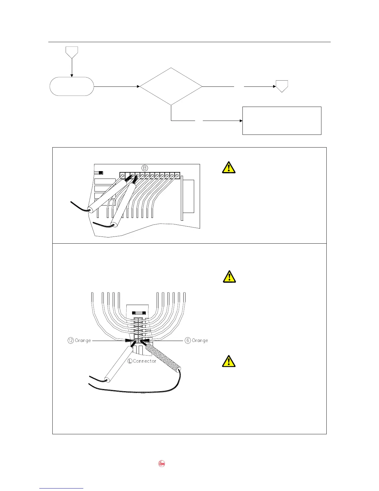
Fault Finding Tests 29 – 31
Test 29 - Diagnostic Point 3
Components will be
“Live” when conducting
tests, exercise caution
Conduct test with water flowing
Measure the voltage between 9
Brown and 10 Black on connector
B.
Voltage should be between DC2 –
5V
Test 30 and 31 - Diagnostic Point 19
Test 30
Isolate power when
conducting resistance
test.
Unplug connector L from the PCB
and measure the resistance
between 6 Orange and 12 Orange.
Resistance should be between
0.6kilo-ohms and 2.8kilo-ohms.
Test 31
Components will be
“Live” when conducting
tests, exercise caution
Conduct test with water flowing
Measure the voltage between 6
Orange and 12 Orange on
connector L.
Voltage should be between DC70 –
110V
 Loading...