70
Gas Supply
IMPORTANT: Any additions, changes or conversions re-
quired for the furnace to satisfactorily meet the application
should be made by a qualified installer, service agency or
the gas supplier, using factory-specified or approved parts.
IMPORTANT: Connect this furnace only to gas supplied by
a commercial utility or commercial fuel provider.
IMPORTANT: U.L. or CSA recognized fuel gas and carbon
monoxide (CO) detector(s) are recommended in all appli-
cations, and their installation should be in accordance with
the manufacturer’s recommendations and/or local laws,
rules, regulations or customs.
Install the gas piping according to all local codes and regu-
lations of the utility company.
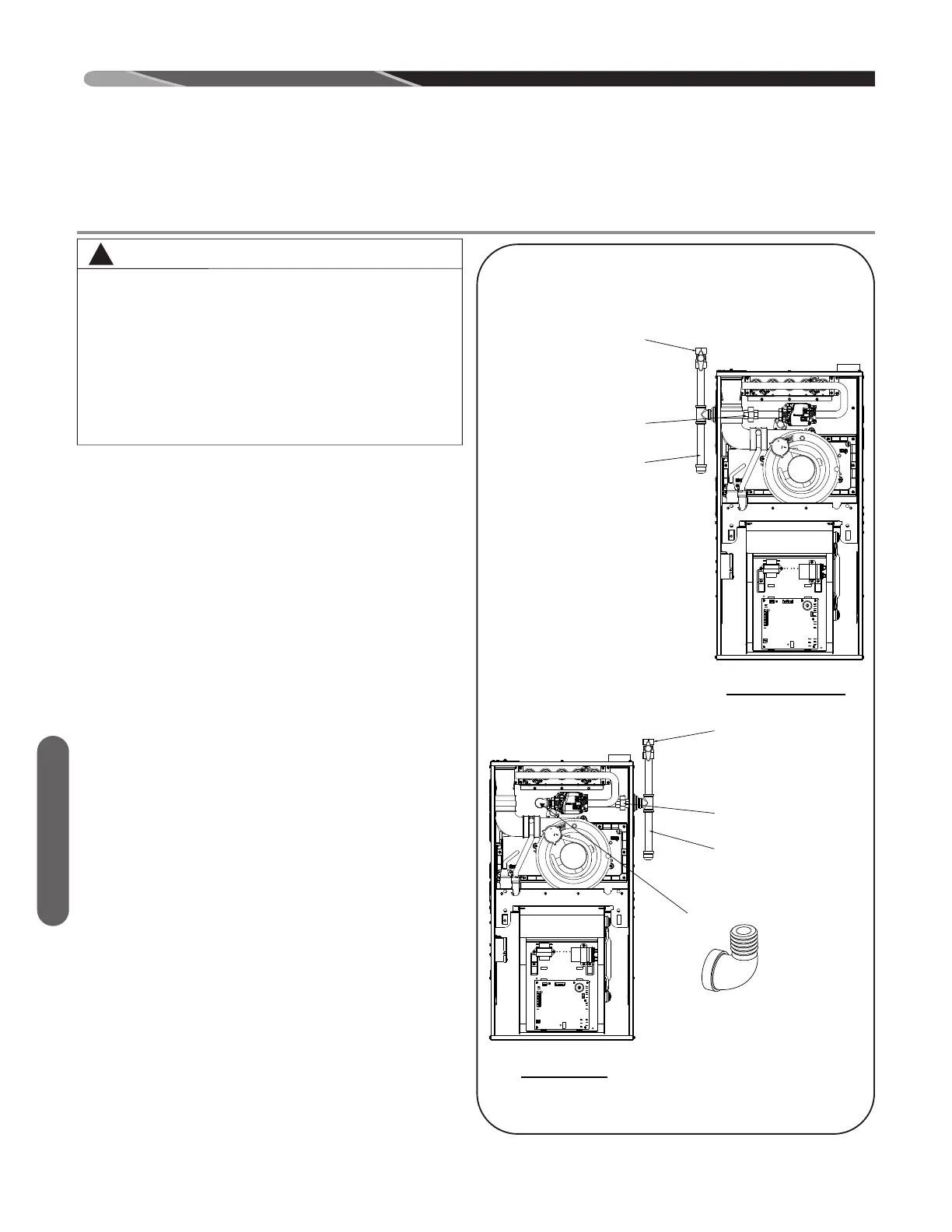
If possible, run a separate gas supply line directly from the
meter to the furnace. Conventional and alternate gas in-
stallations are detailed in Figure 36. Alternate gas from
right of cabinet will require additional fittings. Two street el-
bows are recommended to route gas line behind the valve
and align the knockout in the furnace casing. Consult the
local gas company for the location of the manual main
shut-off valve. The gas line and manual gas stop must
be adequate in size to prevent undue pressure drop
and never smaller than the pipe size to the gas valve
on the furnace. Refer to Table 12 for natural gas (Table
13 for LP gas) for the recommended gas pipe size. See
Figure 36 for typical gas pipe connections.
Install a ground joint union within 3 feet of the cabinet
to easily remove the gas valve assembly. Local codes
may dictate the location of the ground joint union. In-
stall a manul shut-off valve in the gas line outside of
the furnace casing and upstream of the ground joint
union. The manual shut-off valve should be readily acces-
sible to turn the gas supply on or off. Install a drip leg in
the gas supply line as close to the furnace as possible. Al-
ways use a pipe compound resistant to the action of lique-
fied petroleum gases on all threaded connections.
IMPORTANT: When making gas pipe connections, use a
back-up wrench to prevent any twisting of the main gas
valve and manifold. Do not overtighten gas valve on pipe.
Any strains on the gas valve can change the position of
the gas orifices in the burners. This can cause erratic fur-
nace operation.
GAS SUPPLY
GAS PIPING
UPFLOW
FIGURE 36
GAS PIPING INSTALLATION
!
WARNING
THIS FURNACE IS EQUIPPED AT THE FACTORY
FOR USE ON NATURAL GAS ONLY. CONVERSION
TO LP GAS REQUIRES A SPECIAL KIT IS AVAIL-
ABLE AT THE DISTRIBUTOR. FAILURE TO USE THE
PROPER CONVERSION KIT CAN CAUSE FIRE,
CARBON MONOXIDE POISONING, EXPLOSION,
PROPERTY DAMAGE, PERSONAL INJURY OR
DEATH. SEE THE CONVERSION KIT INDEX SUP-
PLIED WITH THE FURNACE. THIS INDEX IDENTI-
FIES THE PROPER LP GAS CONVERSION KIT
REQUIRED FOR EACH PARTICULAR FURNACE.
(CONTINUED ON NEXT PAGE)
ST-A1194-07-02
 Loading...