28
WIRING
WARNING: Turn o electric power
at the fuse box or service panel before making
any electrical connections� Also, the ground
connection must be completed before making line
voltage connections� Failure to do so can result in
electrical shock, severe personal injury, or death�
Control Wiring
Running low-voltage wires in conduit with line
voltage power wires is not recommended� Low-
voltage wiring may be run through the plastic
bushing provided in the 7/8" [19 mm] hole in the
base panel, up to and attached to the pigtails from
the bottom of the control box� Conduit can be
run to the base panel if desired by removing the
insulated bushing�
A thermostat and a 24-volt, 40 VA minimum
transformer are required for the control circuit
of the system� The furnace or the air handler
transformer may be used if sufficient� See the
wiring diagram for reference. Use “Wire Size” table
to size the 24-volt control wiring�
Do not use phone cord to connect indoor and
outdoor units and thermostat� This could damage
the controls and may not be adequately sized for
the controls electrical load�
Control Wiring
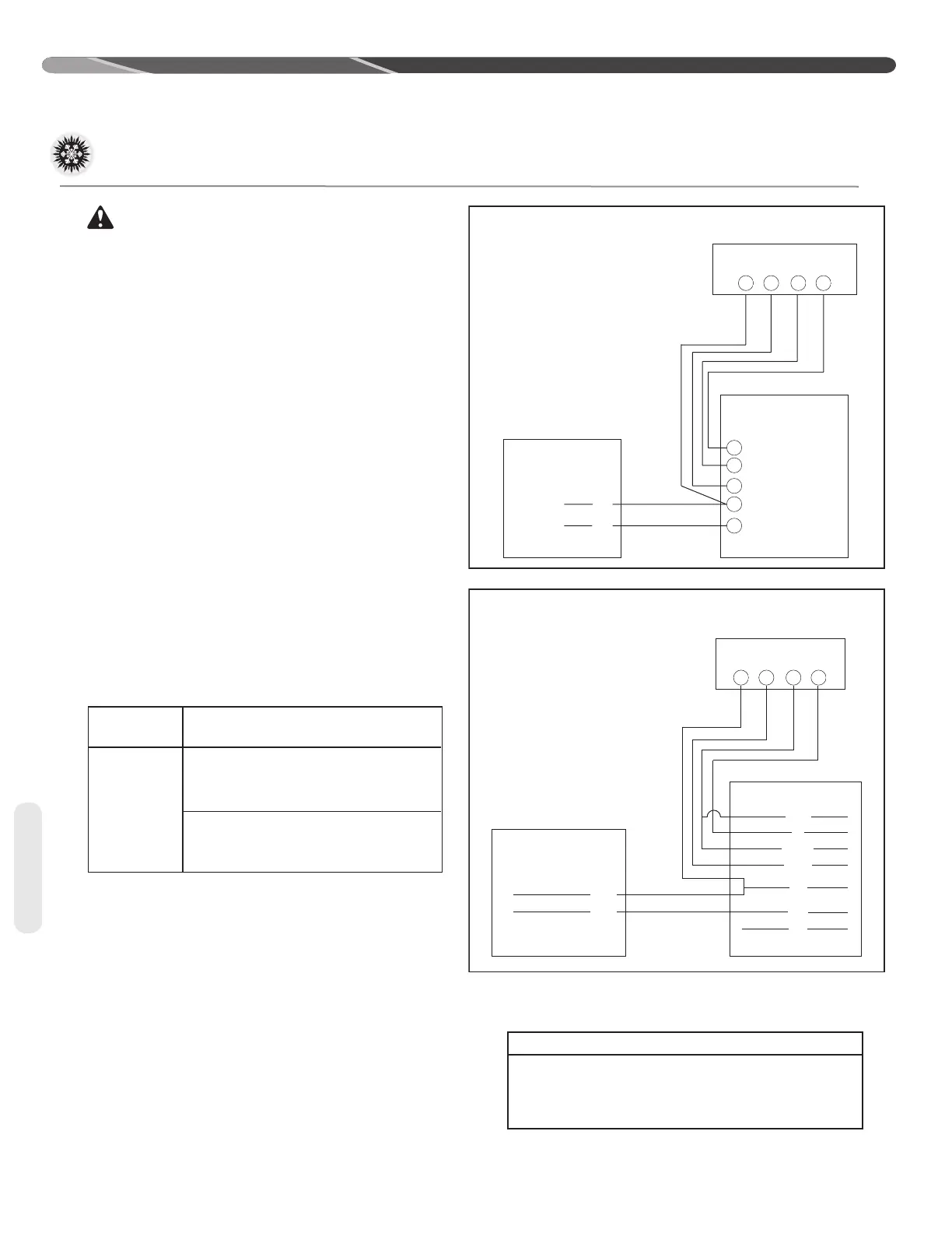
CONTROL WIRING FOR GAS OR OIL FURNACE
FOR TYPICAL GAS OR OIL HEAT
C
Y
G
W
R
YG
W
R
TYPICAL THERMOSTAT
SUBBASE
TYPICAL GAS OR
OIL FURNACE
TYPICAL CONDENSING
UNIT
BR –BROWN WIRE
YL –YELLOW WIRE
X–WIRE CONNECTION
YL
BR
X
X
FOR TYPICAL ELECTRIC HEAT
W/BL
R
W/BK
G/BK
YL
BR
PU
BR –BROWN WIRE
R–RED WIRE
YL –YELLOW WIRE
W/BK –WHITE WIRE WITH BLACK STRIPE
G/BK–GREEN WIRE WITH BLACK STRIPE
PU –PURPLE WIRE (NOT USED)
X–WIRE CONNECTION
*
IF MAXIMUM OUTLET TEMPERATURE RISE IS DESIRED, IT IS RECOMMENDED THAT
W1 (W/BK) AND W2 (W/BL) BE JUMPERED TOGETHER.
TYPICAL CONDENSING
UNIT
YL
BR
X
X
X
X
X
X
X
YG
W
R
TYPICAL THERMOSTAT
SUBBASE
X
TYPICAL ELECTRIC HEAT
LOW VOLTAGE JUNCTION BOX
•
*
FIELD WIRE SIZE FOR 24-VOLT THERMOSTAT CIRCUITS
(1) Wire length equals twice the run distance�
NOTICE: Do not use control wiring smaller than No� 18
AWG between thermostat and outdoor unit�
Typical Noncommunicating
Thermostat Wiring Diagrams
The following figures show the typical wiring
diagrams� Cooling airflows may need to be
adjusted for homeowner comfort once the system
is operational�
WIRE COLOR CODE
BK – BLACK GY – GRAY W – WHITE
BR – BROWN O – ORANGE Y – YELLOW
BL – BLUE PR – PURPLE
G – GREEN R – RED
Wiring
Thermostat
Load (amps)
SOLID COPPER WIRE –AWG.
3.0 18 16 14 12 10 10 10
2.5 18 16 14 12 10 10 10
2.0 18 16 14 12 10 10 10
20 50 100 150 200 250 300
[6] [15] [30] [46] [51] [76] [91]
Length of Run – Feet [m] (1)
 Loading...