EasyManua.ls Logo

Rheem GHE100-160 User Manual

Rheem GHE100-160
61 pages
To Next Page IconTo Next Page
To Previous Page IconTo Previous Page
Page #32 background imageLoading...
Page #32 background image
Error A001 Ignition Lockout (continued)
32
Triton Service Manual SVC1020T ; Rev 4
80 and 100 gallon chassis
Troubleshooting Error Codes
Gas Valve Checking Procedure
Cycle power and/or clear any alarms on the display.
Locate the large black wiring harness plugged into the top of the gas valve.
Loosen the Phillips head screw at the top of the connector, then disconnect it
from the gas valve.
With connector removed, cycle the power on, while display is showing
“IGNITION” check voltage across pins 1 & 5 in the connector. Voltage
reading should be between 10-15VAC. If the voltage reading is correct then
the gas valve is being supplied power and should be operating. If you do not
get 10-15VAC then we could have a faulty gas valve harness or faulty
control board.
Gas Valve Harness and Control Board Checks
Trace the wire harness from the gas valve backwards to P4 connector on the
ignition control board and Disconnect the Molex connector from the P4
connection.
Cycle power and/or clear any alarms. When the display is showing
“IGNITION”, measure for 24 across the outside pins on the P4 connector.
If you get the 24V, then the control board is operating correctly. Replace the
gas valve wiring harness.
If you do not get the 24V, replace the ignition control board.
Is the gas valve working? The best way to confirm the gas valve is operating is with a manometer. Reconnect all
wiring, and connect a manometer to the inlet port of the gas valve. Cycle power and check for a pressure drop
when the unit goes to “IGNITION”. If you have ANY drop at all, the gas valve is opening and allowing gas
flow. (See page 47 for instructions)
If you do not have a manometer available, a less accurate check can be done. With all wiring reconnected, cycle
power on and hold your hand on top of the gas valve solenoid, when the unit goes to “IGNITION” you should
feel a noticeable click.
If you do not get any pressure drop with a manometer and/or do not feel the solenoid click, replace the gas
valve.

Table of Contents

Other manuals for Rheem GHE100-160

Question and Answer IconNeed help?

Do you have a question about the Rheem GHE100-160 and is the answer not in the manual?

Rheem GHE100-160 Specifications

General IconGeneral
BrandRheem
ModelGHE100-160
CategoryWater Heater
LanguageEnglish

Summary

Introduction and Safety

Electrical Shock and Flammable Hazards

Covers electrical shock, flammable liquids, and vapor risks.

Water Temperature Safety

Discusses safe water temperature settings to prevent scalding.

Triton Specifications

Speed Table

Component Parts Overview

Diagrams

Wiring and Schematic Diagram

Presents a block diagram illustrating electrical connections.

Connection Diagram

Illustrates wiring connections between components.

Top View Identification

Shows top view with labeled components.

Parts Identification and Description

Blower, Gas Valve, and Sensors

Describes blower, gas valve, temperature sensors, and anode controller.

Condensate Trap, Ignition, and Controller

Explains condensate trap, igniter, flame probe, main controller, and LCD display.

Switches, Probes, and Leak Sensor

Describes pressure switches, temperature probes, leak sensor, and burner.

User Interface and Operation

Navigation, Startup, and Enabling

Guides through initial setup, enabling, and temperature adjustment.

Settings Menus (Basic, Config, Time/Date)

Covers display, network, differential temp, and time/date settings.

Status, Service, and Wi-Fi Menus

Accesses status, service, alarms, health, and Wi-Fi information.

Alarms and System Health

Shows alarms, provides more info, and details system health status.

Control Board Display Messages

Lists and explains status messages shown on the control board.

Sequence of Operations

Power On and Call for Heat

Describes initial power-up and initiating a heat call.

Pre-purge, Ignition, and Flame Rectification

Covers pre-purge, ignition activation, and flame detection.

Main Burner Operation and Post Purge

Details burner operation and the post-purge cycle.

Stand-By Mode Operation

Describes the idle state and how the unit calls for heat.

Safety Functions of Controls

Flame Detection and ECO Function

Explains flame detection and the Energy Cut Off switch.

Pressure Switches and Vent Temperature Sensor

Explains pressure switches and the vent temperature sensor's roles.

Power Outages and Ignition Retries

Covers auto-resume after power loss and ignition retry logic.

Condensate Removal System

Describes the condensate removal tube and its maintenance.

Error Codes

Troubleshooting Error Codes

Ignition Lockout and Flame Stability (A001-A002)

Details ignition lockout failures and unstable flame issues.

Intake Switch and PoF Switch Errors (A003-A008)

Addresses intake switch and PoF switch errors.

Temperature and Blower Errors (A017-A026)

Covers temperature sensor, flue temp, blower feedback, and RPM mismatch errors.

Communication and Controller Errors (A031-A044)

Troubleshoots anode communication, relay, and controller errors.

Time Clock, Leak, and Valve Errors (A101-A121)

Addresses time clock, leak detection, and shut-off valve errors.

Anode Alerts (T122-T137)

Troubleshooting guidance for powered anode controller communication and alerts.

Maintenance Procedures

Gas Pressure Checking

Procedure for checking inlet gas pressure and verifying flow.

Gas Valve Adjustment

Steps for adjusting the gas valve for optimal CO2 levels.

Disassembly and Repair

Component Replacement Guides

Instructions for replacing ignition board, LCD, blower motor, temp sensor, igniter, flame sensor, switches, and exhaust sensor.

Replacing the Burner Assembly

Step-by-step guide for removing and installing the burner assembly.

BACnet Configurations

BACnet Protocol and Setup Overview

Introduces BACnet capability, protocol, and accessing configuration settings.

BACnet Quick Start Guide and Settings Details

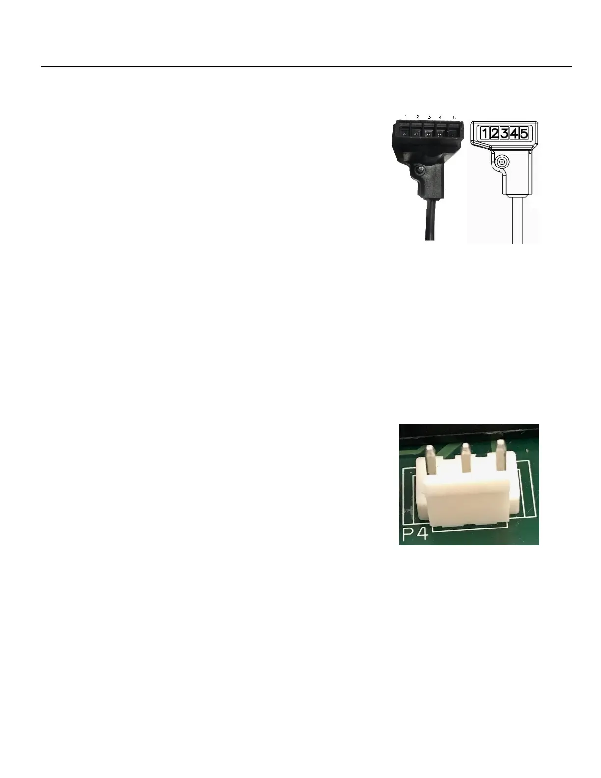
Provides pinout, instructions, and details for BACnet settings.

Leak Guard System

What is LeakGuard?

Explains the proprietary auto shut-off system for leak prevention.

Related product manuals