20
Vertical Vent and Combustion Air-Inlet Installation
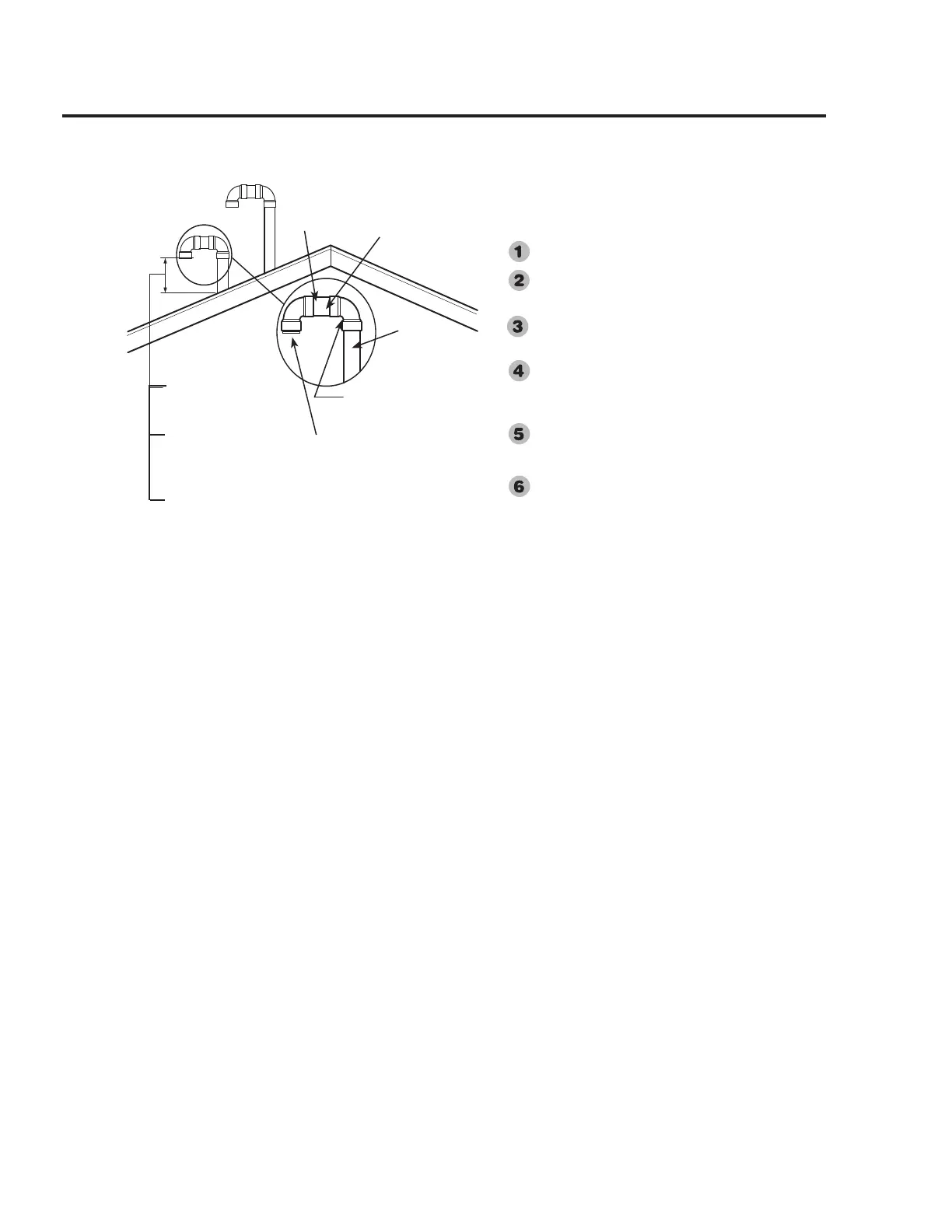
The location of the vent and combustion air-inlet termi-
nals depends on the following minimum clearances and
considerations.
Minimum 12 in. (30.5 cm) above roof.
Minimum 12 in. (30.5 cm) above anticipated snow
level.
Maximum 24 in. (61cm) above roof level without
additional support for vent.
Four (4) ft. (1.22 m) from any gable, dormer or other
roof structure with building interior access (i.e., vent,
window, etc.).
Ten (10) ft. (3.05m) from any forced air inlet to the
building. Any fresh or make-up air inlet such as a
dryer or furnace area is considered to be a forced air
inlet.
Maintain a minimum distance of 12 in. (30.5 cm)
between the vent and combustion air-inlet terminal cen-
terlines.
Min. 12 in. (30.5 cm)
Above Roof
Min. 12 in .(30.5 cm )
Above Anticipated Snow
Level.
Max. 24 in. (61 cm) Above
Roof (Without Additional
Support)
Terminals with ½” Mesh Protective
Screen and Termination Restrictor
Inside. Note: Termination Restrictors
used on 75 Gallon models ONLY.
Vent Pipe or
Combustion
Air-Inlet
Through Roof
Elbow
Vent and/or Combustion
Air-Inlet Terminal
Short Piece of Pipe
Important: The vent terminal must not terminate below
the combustion air-inlet terminal.
Exhaust Vent
Combustion
Air-Inlet
Determine the locations for the vent and com-
bustion air-inlet terminals then make two (2)
holes through the roof and interior ceiling(s)
to accommodate the vent and combustion air-
inlet pipes. Maintain a minimum distance of
16 in. (40.6 cm) between the vent and com-
bustion air-inlet terminals.
Install the vent system and attach it to the vent
connector fitting on the water heater’s blower
assembly. Horizontal lengths of the vent
system must slope downward away from the
water heater a minimum of 1/8 in. per foot (10
mm per meter).
Install the combustion air-inlet system and
attach it to the combustion air-inlet connector
fitting on the water heater’s combustion air-
inlet tube assembly. Horizontal lengths of the
combustion air-inlet system must slope down-
ward from the water heater a minimum of 1/8
in. per foot (10 mm per meter).
Support vertical and horizontal lengths of the
vent and combustion air-inlet systems as pre-
viously mentioned.
Determine the vent and combustion air-inlet
terminal heights and cut the pipe accordingly.
Insert lengths of vent and combustion air-
inlet pipes through the ceiling wall as shown.
Install adequate flashing where the vent and
combustion air-inlet pipes pass through the
roof.
Place the supplied ½ in. (1.3 cm) mesh metal
screens inside each terminal fitting then con-
nect a short piece of pipe approximately 3 in.
(7.6 cm) to the terminals and elbows.
For 75 Gallon Power Direct Vent Models
ONLY:
These water heater models are supplied with
two (2) vent and combustion air-inlet termina-
tion restrictors. These restrictors help main-
tain the efficiency of the water heater when
installed using 3 in. (7.6 cm) diameter pipe
at the minimum equivalent vent and combus-
tion air-inlet lengths specified in Table 2.
The termination restrictors must be installed
in the same location as the supplied vent
and combustion air-intake terminal screens.
IMPORTANT: Do not install the termination
restrictors in equivalent vent and/or combus-
tion air-inlet lengths longer than 8 feet (2.44
meters) or on any other Power Direct Vent
model.
Installing the Water Heater
 Loading...