23
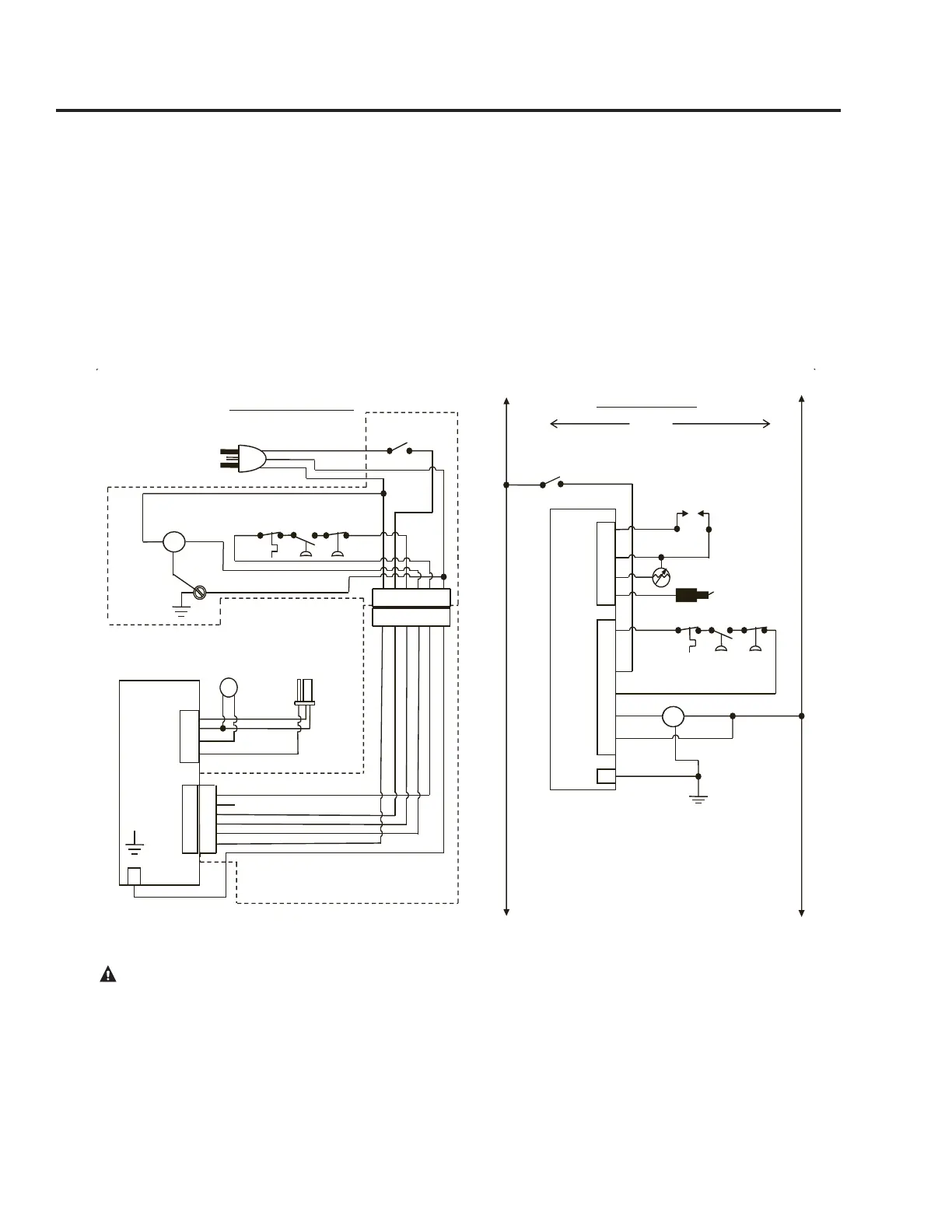
Wiring
If local codes permit, the water heater may
be connected to electric service with the
power cord provided (DO NOT use an
extension cord). A grounding receptacle is
required.
If local codes do not permit the use of
cord connections, a 120 V, 50/60 Hz
power supply, with suitable disconnecting
means, must be connected to the black and
white leads in the heater control enclosure.
The maximum current draw is less than
5.0 amps.
The water heater must be electrically
grounded in accordance with local codes,
or, in the absence of local codes, in accor-
dance with latest edition of the National
Electric Code ANSI/NFPA No. 70. Refer
to the figures below for water heater inter-
nal wiring.
CAUTION! Label all wires prior to disconnection when servicing controls. Wiring errors can cause improper and
dangerous operation. VERIFY PROPER OPERATION AFTER SERVICING!
1
2
3
4
5
6
J2
1
2
3
4
1
2
3
4
5
6
GAS VALVE
SOUPAPE DE GAZ
INTELLI-VENT ELECTRONIC CONTROL
CONTRÔLE ÉLECTRONIQUE INTELLI-VENT
BK
W
W
W
BK
1 2 3 4 5 6
1 2 3 4 5 6
W R R Y BL G
WIRE HARNESS THAT RUNS FROM BLOWER ASSEMBLY
TO WIPER CONTROL GAS VALVE
FAISCEAU DE CÂBLAGE ENTRE L’ENSEMBLE DU
SOUFFLEUR ET LA INTELLI-VENT DE LA SOUPAPE DE
CONTRÔLE DU GAZ
ANY REPLACEMENT IGNITOR CABLE MUST BE RATED AT 250º C
TOUT CÂBLE D’ALLUMAGE DE REMPLACEMENT DOIT ÊTRE
ÉTALONNÉ Á 250º C
IGNITER AND
FLAME SENSOR
ALLUMEUR ET
CAPTEUR DE
FLAMME
FLAMMABLE
VAPOR SENSOR
DÉTECTEUR DE
VAPEUR
INFLAMMABLE
H
G
N
120 VAC PLUG FOR POWERVENT
BLOWER ASSEMBLY
PRISE DE 120 VCA POUR
L’ENSEMBLE DE
SOUFFLEUR D’ÉVENT MÉCHANIQUE
POWER
VENT BLOWER
ASSEMBLY
ENSEMBLE DU
SOUFFLEUR
D’ÉVENT
MÉCANIQUE
BLOWER
SOUFFLEUR
CONTACTEUR À
DÉPRESSION
6 PIN CONNECTOR
CONNECTEUR À
6 BROCHES
W
BK R Y BL G
CONNECTOR DIAGRAM
SCHÉMA DES CONNEXIONS
SCREW
GND VIS
DE MISE
À LA TERRE
H
N
1
2
3
4
5
6
1
2
3
4
GAS VALVE
SOUPAPE DE GAZ
INTELLI-VENT ELECTRONIC CONTROL
CONTRÔLE ÉLECTRONIQE INTELLI-VENT
BK
W
W
W
BK
GND
MOT
120 VAC
H N
SCHEMATIC DIAGRAM
SCHÉMA DE CABLÂGE
BL
N/C
R
R
W
Y
MOT
BLOWER
SOUFFLEUR
NOTE: IF ANY OF THE ORIGINAL WIRE SUPPLIED WITH THE APPLIANCE
MUST BE REPLACED, IT MUST BE REPLACED WITH A 18 GA, 600 V,
105º C WIRE.
REMARQUE: SI UNE PARTIE QUELCONQUE DU CÂBLAGE ORIGINAL
FOURNI AVEC L’APPAREIL DOIT ÊTRE REMPLACÉE, ELLE DOIT ÊTRE
REMPLACÉE AVEC UN FIL DE CALIBRE 18, 600 VCA, 105º C.
BK = BLACK/NOIR
BL = BLUE/BLEU
G = GREEN/VERT
R = RED/ROUGE
W = WHITE/BLANC
Y = YELLOW/JAUNE
BK
G
W
FV
VAC
SW NO
VAC
SW NC
TEMPERATURE
SWITCH NC
CHANGEMENT DE
TEMPÉRATURE
ON/OFF SWITCH
CONTACTEUR
MARCHE/ARRÉT
IGNITER
ALLUMEUR
FLAMMABLE VAPOR SENSOR
DÉTECTEUR DE VAPEUR INFLAMMABLE
FLAME SENSOR
CAPTEUR DE FLAMME
ON/OFF
SWITCH
CONTACTEUR
MARCHE/ARRÉT
VAC
SW NO
VAC
SW NC
TEMPERATURE
SWITCH NC
CHANGEMENT DE
TEMPÉRATURE
CONTACTEUR
À DÉPRESSION
N/C
GND
BL
R
R
Y
W
G
 Loading...