16
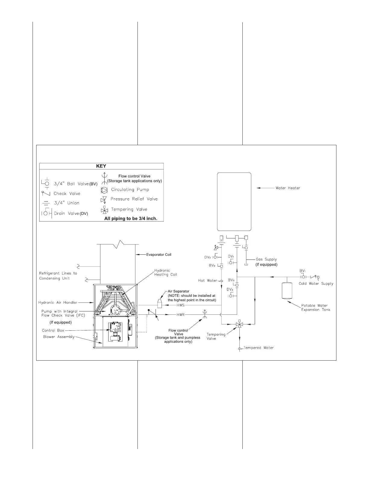
FIGURE 11
TYPICAL PIPING ARRANGEMENT FOR DIRECT SPACE HEATING AND DOMESTIC WATER SUPPLY WITH TANKLESS
Open-Loop System
If piping is done in accordance with the
recommended schematic diagram
shown in Figure 10, the following purge
and priming procedure applies.
PURGING AND PRIMING THE
SYSTEM:
The following procedure describes how
the system may be piped to eliminate
the need for a “purge cart” to fill the
system and remove entrapped air
bubbles.
STEP 1: CLOSE the air separator
venting valve.
STEP 2: CLOSE ball valve 3 (BV
3);
STEP 3: OPEN drain valve 3 (DV
3) to
which a hose MUST be connected and
draining to a sink, drain or outdoors.
STEP 4: CLOSE drain valves 1 & 2
(DV
1 and DV2) and OPEN ball valve 2
(BV
2).
STEP 5: OPEN cold water supply main
valve (ball valve 1 - BV
1). The system
will begin the prime/purge process using
the street pressure. Entrapped air
bubbles being pushed out of the system
will be evident by a slight vibration of the
discharge hose connected to drain valve
3 (DV
3). The hose will stop vibrating
when laminar flow is achieved.
STEP 6: CLOSE drain valve 3 (DV
3);
STEP 7: OPEN ball valve 3 (BV
3).
The system is now purged, primed
and ready to go.
STEP 8: OPEN the air separator
venting valve.
NOTE: For an open-loop system, use
expansion tank approved for potable
water use only.
ST-A1242-08-00
 Loading...