9
SELECTION PROCEDURE
(WITH EXAMPLE)
I. Define hot water load for the total
required domestic hot water
usage.
As an example, let’s assume that the
selected Tankless Water Heater for your
whole house solution is the RTG-74 and
your calculated heat gain and heat loss
values are as stated in section II.
II. Determine cooling and heating
requirements at design conditions:
The ACCA’s Manual J Residential Load
Calculation method is the established
trade standard, approved by ANSI, for
the correct siziing and selection of
Heating, Ventilation, Air-Conditioning
and Refrigeration (HVACR) equipment in
residential homes. The most recent
revision is the eight edition, an all-
inclusive new approach to ensuring that
Indoor Air Quality (IAQ) systems are as
efficient, safe, and healthy as possible.
Refer to the Air Conditioning Contractors
of America website at:
http://www.acca.org/tech/manualj/
or a
qualified HVACR contractor for further
assistance.
Assumptions:
Required Cooling Capacity . 48,000 BTU/HR
(Total Capacity)
Required Heating Capacity . 60,000 BTU/HR
Evaporator Air Quantity. . . . . . . . . 1600 CFM
External Static Pressure . . . . . . . 0.2 in. W.C.
Electrical Characteristics . . . . . . . . . 115-1-60
III. Determine total external static
pressure (ESP) at design
conditions:
Before using the Airflow Performance
Table calculate the total static pressure
required. From the given example, note
the Wet Coil Pressure Drop (selected
from the field supplied Evaporative
Cased Coil Installation Instructions), and
the Filter Pressure Drop. Determine both
static pressures at 1600 CFM:
Wet Coil Pressure Drop . . . .0.3 in. W.C.
(From Coil Manufacturer’s Installation Instructions)
External Static Pressure . . . 0.2 in. W.C.
(Ductwork, etc.)
Filter Pressure Drop . . . .08 in. W.C.
(.08 inches if the included filter is used; refer to
the filter’s manufacturer’s instructions if another
filter is used.)
Total Static Pressure. . . 0.58 in. W.C.
IV. Select unit based on required
cooling capacity airflow:
For an initial selection, choose a unit
size that will provide the required
airflow. Refer to Airflow Performance
Table. Note that at 0.6 ESP (external
static pressure) the
RW1T06A3617NAA unit will deliver
1560 CFM when configured for HIGH
speed.
V. Select heating capacity of unit
to provide the requisite design
condition:
From the Hydronic Air Handler/
Tankless Water Heater, note that the
unit RW1T06A3617NAA, (as selected
above) when matched with the RTG-
95 Tankless Water Heater, will
provide 59.2 MBH (59,200 BTU/HR)
at an input water temperature (to Air
Handler) of 150°F.
3
2
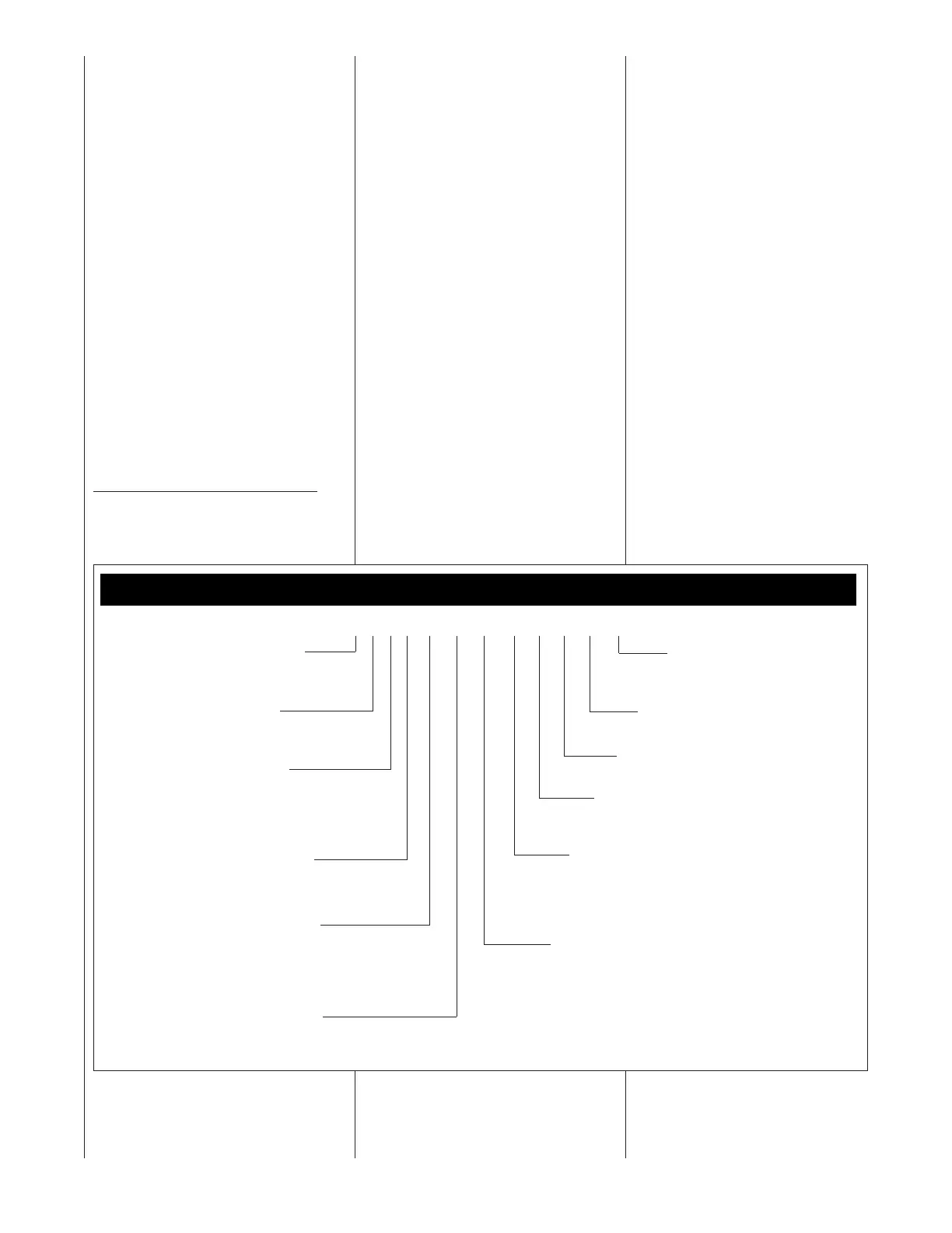
Model Number Nomenclature
3 08 K A 5
M
RW1 T 04 A 24 14 N A A ***
TRADE BRAND
R = RHEEM
PRODUCT CATEGORY
W = HYDRONIC AIR HANDLER
STAGE OF AIR FLOW
1 = SINGLE
2 = TWO STAGE
M = MODULATING
MOTOR TYPE
T = CONSTANT TORQUE
V = VARIABLE SPEED
P = PSC
NOMINAL CAPACITY
04 = 40,000 BTU/H
06 = 60,000 BTU/H
08 = 80,000 BTU/H
10 = 100,000 BTU/H
MAJOR SERIES
A = FIRST
OPTION CODE
BLANK = NONE
415 = WITHOUT PUMP
WIDTH
14 = 14”
17 = 17.5”
21 = 21”
24 = 24.5”
MAX COOLING AIRFLOW TONNAGE
24 = UP TO 2 TON
36 = UP TO 3 TON
48 = 2.5 TO 4 TON
60 = 3 TO 5 TON
VOLTAGE
A = 115/1/60
CONTROLS
C = COMMUNICATING
N = NON-COMMUNICATING
MINOR SERIES
A = FIRST
 Loading...