20
INSTALLATION
4.12.5 Adjusting and Setting O2 Limits
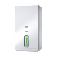
− Insert a combustion analyzer probe into the test port
shown in Fig. 15
− Go to the Touchscreen and access the Module screen (as
described on “6.3.4 Module Screen” page 32) relevant to
the module under analysis;
− Press “MODULE TEST” button;
− Press “HIGH POWER” button.
Wait 2 or 3 minutes to reach steady state conditions and record
the O
2 value.
Test port of
the module
Fig. 15
Test Port for Combustion Analysis (available on each
individual heat exchanger)
To adjust the O2 value at the maximum power turn the screw “A”
(rotate counter-clockwise to decrease O
2) shown in Fig. 16, allen
type wrench is necessary for this adjustment.
Verify that the value of O
2 is stable and is within the range
indicated in the following table (be careful to make small changes
and conrm that the value is stable before making additional
adjustment).
Press “LOW POWER”: the fan will run at the minimum speed.
Fig. 16
O
2
Adjustment
To adjust the O2 value at the minimum input, turn the screw “B”
(rotate clockwise to decrease O
2) shown in Fig. 16.
Verify that the value of O
2 is stable and is within the range
indicated in the following table (be careful to make small changes
and conrm that the value is stable before making additional
adjustment).
Press “Reset” and the boiler return to the “stand by” mode.
Repeat the above process for all heat exchangers.
Array Combustion Values
Gas Type Max. Fire O
2% Min. Fire O2%
Natural Gas 4.2 – 5.8 4.2 – 5.8
LP Gas 5.4 – 10.2 5.4 – 10.2
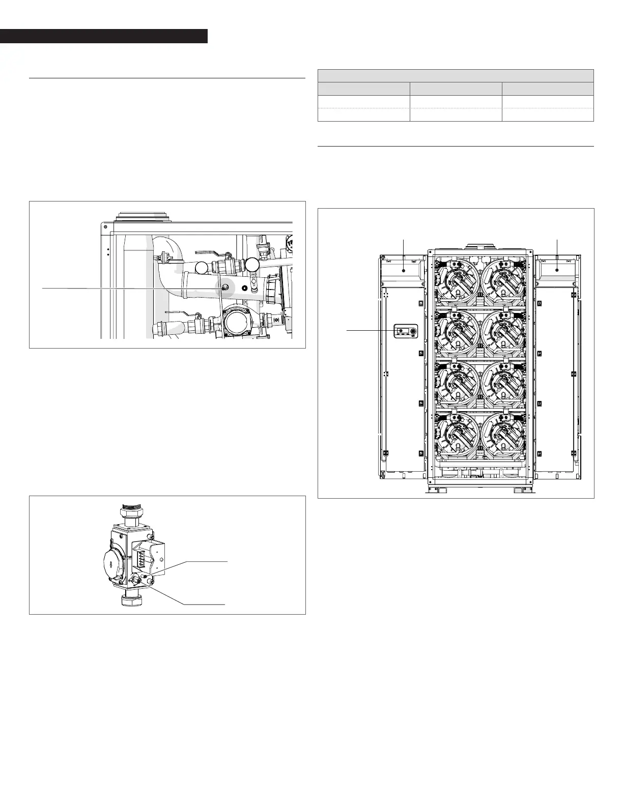
4.13 AC Electrical Power Wiring
External AC power connections are made to the unit inside the
electrical box, located on the inside of the front doors. Open the
front doors and remove the panel mounted in the upper part of
the left front door of the unit as shown in Fig. 16.
Cover Panel
Right Door
Cover Panel
Fig. 17
Front Doors Internal Layout
Loosen the screws of the cover and remove panel to access the
internal connections shown in Fig. 18.
 Loading...