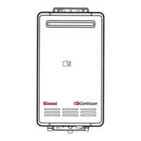
REU-2532FFU Series 55 Rinnai
IMPORTANT
When dismantling the unit you should always isolate
the following items.
• Gas supply.
• Electrical supply.
• Water supply.
• Drain all water from the appliance.
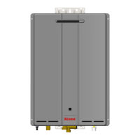
The following diagram may be of assistance in
locating the above.
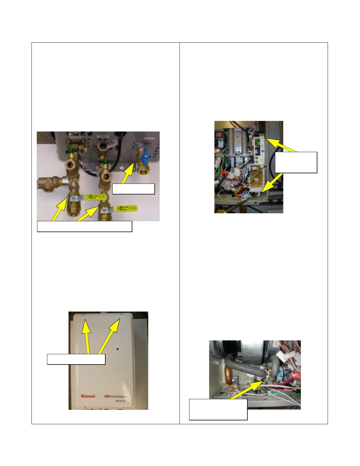
1. Removal of the Front Panel
CAUTION
120 volt potential exposure. Isolate the appliance and
reconfirm power has been disconnected using a multi-
meter.
a. Remove the four (4) screws holding the panel in
place with a Phillips driver.
2. Removal of PC board
CAUTION
120 volt potential exposure. Isolate the appliance and
reconfirm power has been disconnected using a multi-
meter.
a. Remove the two (2) screws holding the PCB in
place with a Phillips screw driver, then pull the
PC board out of the appliance.
Disconnect all connectors.
3. Removal of the Water Flow Sensor and Water
Flow Control Valve Assembly
CAUTION
120 volt potential exposure. Isolate the appliance and
reconfirm power has been disconnected using a multi-
meter.
a. Remove one (1) Phillips screw from the heat exchanger
water supply line and (1) screw from the bypass valve
assembly. Lift the water line retainer up and over the
housing it attaches too, pull water line towards yourself
to disconnect water lines from the assembly. Inspect o-
rings for damage, replace if defective.
Water flow sensor
and servo assembly
Front cover screws.
Cold and hot water shut-off valves
Gas shut-off
P.C. board
screws
 Loading...