FLEX I/O Digital DC Output Modules 9
Publication 1794-IN094D-EN-P - July 2018
Connect Wiring for 1794-OB8, 1794-OB8EP, 1794-OB16, and 1794-OB16P
1. Connect individual output wiring to numbered terminals on the 0-15 row (A) as
indicated in the table below 1794-OB8 – Terminals 0...7; 1794-OB16 and
1794-OB16P – terminals 0...15; 1794-OB8EP – even numbered terminals
0...14.
2. Connect the associated -V output common to the corresponding terminal on the
16…33 row (B) for each output as indicated in the table below. Commons are
internally connected together.
1794-OB8EP – connect associated output common to odd-numbered terminals
on row A or associated terminals on row (B).
3. Connect +V DC power to terminal 34 on the 34…51 row (C).
4. Connect -V DC common to terminal 16 on the 16…33 row (B).
5. If daisychaining power to the next terminal base, connect a jumper from terminal
51 (+V DC) on this base unit to terminal 34 on the next base unit.
6. If continuing -V DC common to the next base unit, connect a jumper from
terminal 33 (common) on this base unit to terminal 16 on the next base unit.
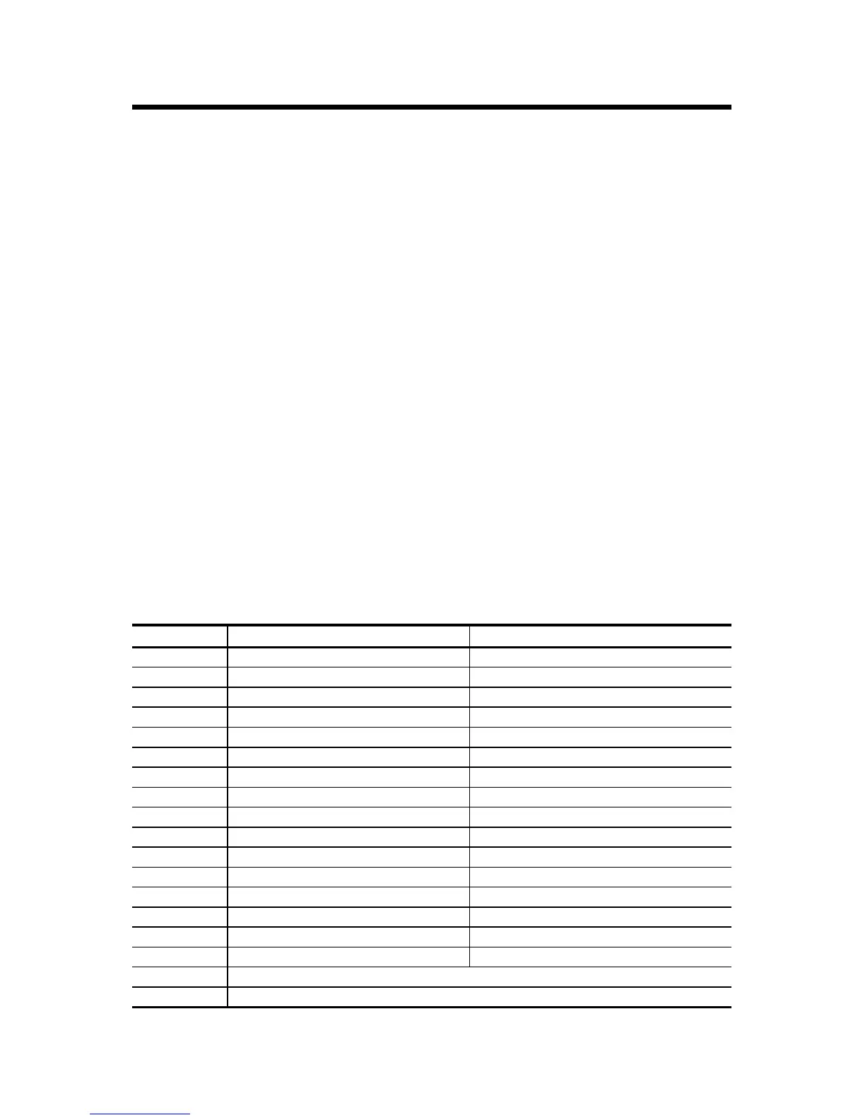
Wiring Connections for 1794-OB8, 1794-OB16, and 1794-OB16P
used with 1794-TB2, 1794-TB3, or 1794-TB3S Terminal Base Unit
Output
(1)
(1)
1794-OB8 – Outputs 0...7; 1794-OB16 and 1794-OB16P – Outputs 0...15
Output Terminal Common Terminal
Output 0 A-0 B-17
Output 1 A-1 B-18
Output 2 A-2 B-19
Output 3 A-3 B-20
Output 4 A-4 B-21
Output 5 A-5 B-22
Output 6 A-6 B-23
Output 7 A-7 B-24
Output 8 A-8 B-25
Output 9 A-9 B-26
Output 10 A-10 B-27
Output 11 A-11 B-28
Output 12 A-12 B-29
Output 13 A-13 B-30
Output 14 A-14 B-31
Output 15 A-15 B-32
+V DC C-34…C-51 (C-34 and C-51 for 1794-TB2)
Common B-16…B-33

 Loading...


