6 Rockwell Automation Publication 1734-IN032F-EN-P - September 2022
POINT I/O 4 Channel High Density Current Input Module Installation Instructions
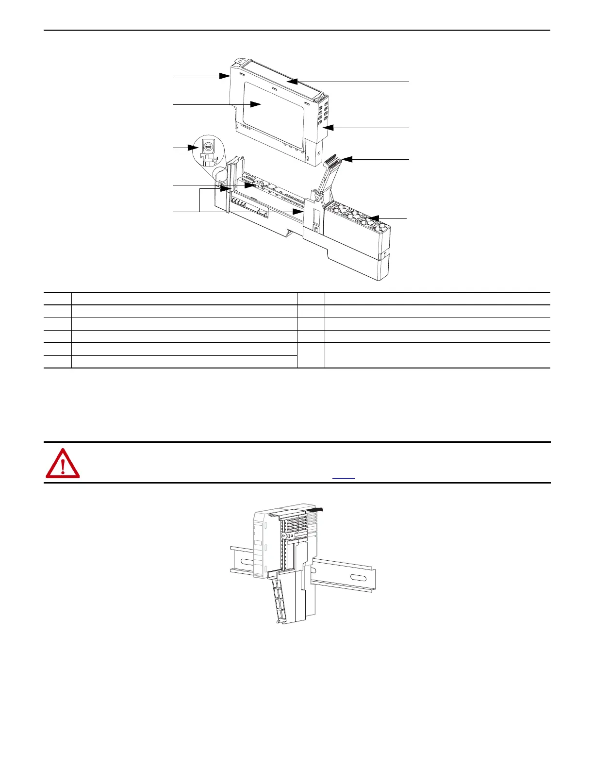
Figure 2 - POINT I/O 4 Channel High-Density Current Input Module with 1734-TOP or 1734-TOPS Base
Install the Mounting Base
To install the mounting base on the DIN rail (Allen-Bradley® part number 199-DR1; 46277-3; EN50022), proceed as follows:
1. Position the mounting base vertically above the installed units (adapter, power supply or existing module).
2. Slide the mounting base down allowing the interlocking side pieces to engage the adjacent module or adapter.
3. Press firmly to seat the mounting base on the DIN rail. The mounting base snaps into place.
4. To remove the mounting base from the DIN rail, remove the module, and use a small bladed screwdriver to rotate the base locking screw to a vertical position. This releases
the locking mechanism. Then lift straight up to remove.
Description Description
1 Module locking mechanism 6 Interlocking side pieces
2 Slide-in writable label 7 Mechanical keying (orange)
3 Insertable I/O module 8 DIN rail locking screw (orange)
4 Removable terminal block (RTB) handle
9Module wiring diagram
5 One-piece terminal base with screw or spring clamp – 1734-TOP, 1734-TOPS
ATTENTION: This product is grounded through the DIN rail to chassis ground. Use zinc-plated chromate-passivated steel DIN rail to assure proper grounding.
The use of other DIN rail materials (for example, aluminum or plastic) that can corrode, oxidize, or are poor conductors, can result in improper or intermittent
grounding. Secure DIN rail to mounting surface approximately every 200 mm (7.8 in.) and use end-anchors appropriately. Be sure to ground the DIN rail
properly. See the Industrial Automation Wiring and Grounding Guidelines, publication 1770-4.1, for more information.

 Loading...


