English-8 PowerFlex 400P Adjustable Frequency AC Drive Quick Start
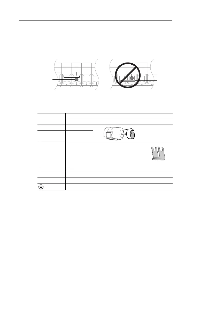
Important: For Frame E, 480V 55-75 kW (75-100 HP) drives, take care
to place the wire beneath the jumper and not above it when
connecting to terminals P1 and P2.
Terminal
(1)
Description
R/L1, S/L2, T/L3 3-Phase Input
U/T1 To Motor U/T1
=
Switch any two motor
leads to change
forward direction.
V/T2 To Motor V/T2
W/T3 To Motor W/T3
P2, P1
DC Bus Inductor Connection
Drives are shipped with a jumper between Terminals
P2 and P1. Remove this jumper only when a DC Bus
Inductor will be connected. Drive will not power up
without a jumper or inductor connected.
DC–, DC+ DC Bus Connection (Frame C and H Drives)
P2, DC– DC Bus Connection (Frame D, E, F and G Drives)
BR+, BR– Not Used
Safety Ground - PE
(1)
Important: Terminal screws may become loose during shipment. Ensure that all
terminal screws are tightened to the recommended torque before applying power to
the drive.
P1 P2 DC- P1 P2 DC-
Wire
Jumper
Wire
Jumper
Correct
Incorrect
Bottom view of terminal block and wire
22P-QS001C-EN-P.fm Page 8 Thursday, March 30, 2017 5:55 PM
 Loading...


