PowerFlex 400P Adjustable Frequency AC Drive Quick Start English-3
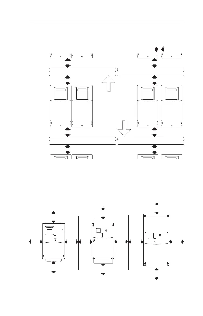
Minimum Mounting Clearances
Figure 1: Frame C Mounting Clearances
Figure 2: Frames D, E, F, G, and H Mounting Clearances
120 mm
(4.7 in.)
120 mm
(4.7 in.)
25 mm
(1.0 in.)
120 mm
(4.7 in.)
120 mm
(4.7 in.)
120 mm
(4.7 in.)
120 mm
(4.7 in.)
120 mm
(4.7 in.)
120 mm
(4.7 in.)
Mounting Option BMounting Option A
No clearance required
between drives.
Closest object that
may restrict air flow
through the drive heat
sink and chassis.
150 mm
(6.0 in.)
150 mm
(6.0 in.)
50 mm
(2.0 in.)
250 mm
(9.8 in.)
150 mm
(6.0 in.)
300 mm
(11.8 in.)
300 mm
(11.8 in.)
300 mm
(11.8 in.)
300 mm
(11.8 in.)
50 mm
(2.0 in.)
50 mm
(2.0 in.)
50 mm
(2.0 in.)
Frame D and E Frame F Frame G and H
22P-QS001C-EN-P.fm Page 3 Thursday, March 30, 2017 5:55 PM
 Loading...


