17
Publication 1763-IN001C-EN-P - June 2015
Wiring the Controller
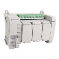
Terminal Block Layouts
The shading in the following terminal block illustrations indicates
which terminals are tied to which commons.
AC
COM
NOT
USED
VAC O/0
VDC
VAC O/1
VDC
VAC O/2
VDC
VAC O/3
VDC
VAC O/4
VDC
VAC O/5
VDC
NOT
USED
NOT
USED
L1 L2/N
100-240 VAC
NOT
USED
I/1I/0 I/2 I/3
AC
COM
I/4 I/5
IA
COM
IV1(+) IV2(+)I/6 I/7 I/8 I/9
1763-L16AWA Input Terminal Block
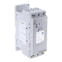
Output Terminal Block
DC
COM-
VAC O/0
VDC
VAC O/1
VDC
VAC O/2
VDC
VAC O/3
VDC
VAC O/4
VDC
VAC O/5
VDC
NOT
USED
NOT
USED
L1 L2/N
100-240 VAC
DC OUT
+ 24V
I/1I/0 I/2 I/3
DC
COM
I/4 I/5
IA
COM
IV1(+) IV2(+)I/6 I/7 I/8 I/9
1763-L16BWA Input Terminal Block
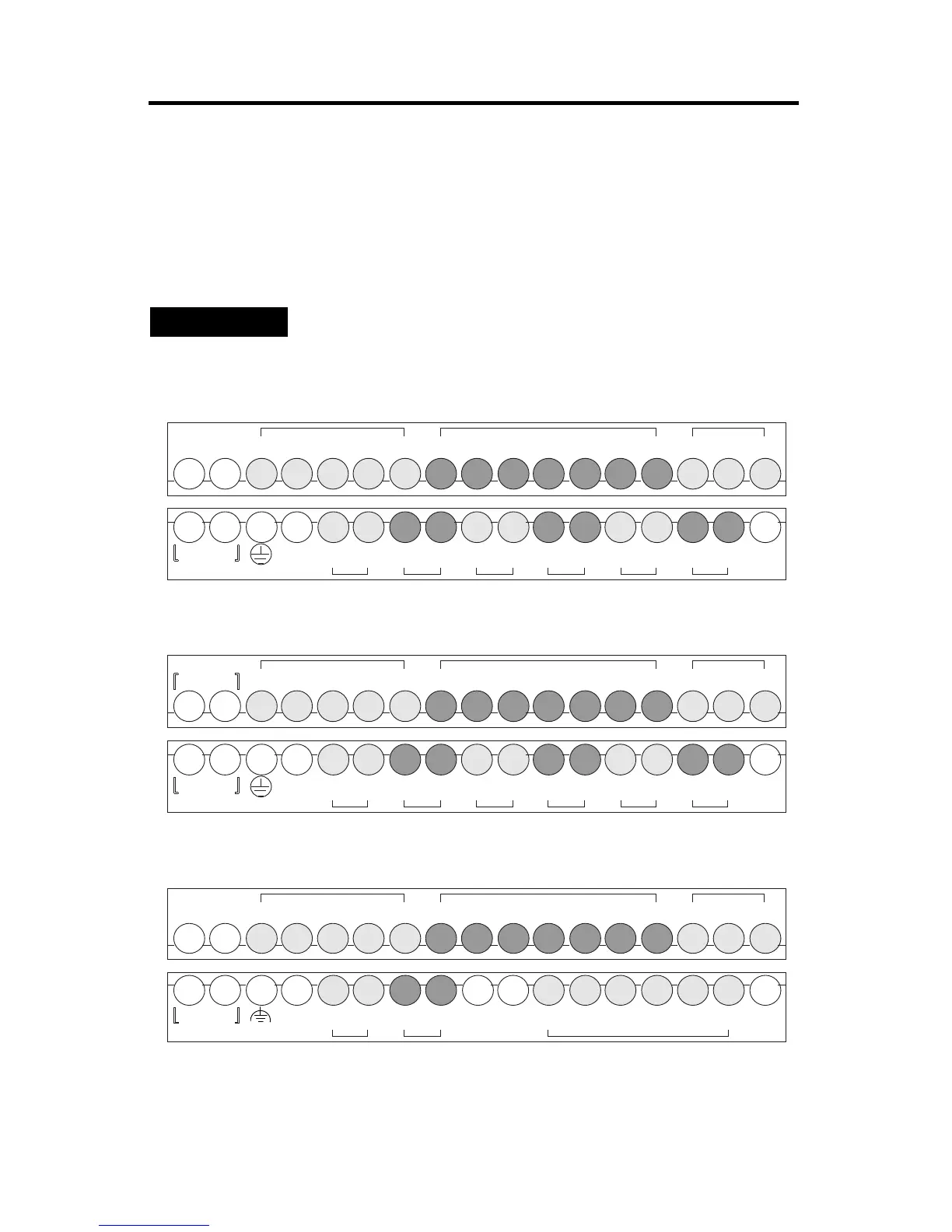
Output Terminal Block
DC
COM
NOT
USED
VAC O/0
VDC
VAC O/1
VDC
NOT
USED
NOT
USED
DC O/2 O/3
24V+
DC
24V-
O/4 O/5NOT
USED
NOT
USED
+ 24V -
DC IN
NOT
USED
I/1I/0 I/2 I/3
DC
COM
I/4 I/5
IA
COM
IV1(+) IV2(+)I/6 I/7 I/8 I/9
1763-L16BBB Input Terminal Block
Output Terminal Block
 Loading...